#Product Trends
Integrating Inertial Sensors into Defense Navigation Systems
In modern defense applications, relying solely on Global Navigation Satellite Systems (GNSS) presents a vulnerability due to the high likelihood of jamming and spoofing.
In modern defense applications, relying solely on Global Navigation Satellite Systems (GNSS) presents a vulnerability due to the high likelihood of jamming and spoofing.
To maintain full-state, low-latency control, such as tracking position, velocity, and attitude (roll, pitch, and heading), engineers require systems capable of constant, reliable positional accuracy.
This is where self-contained, navigation systems become essential.
What Are Inertial Sensors and How Do They Work?
An IMU sensor typically consists of gyroscopes and accelerometers designed to measure angular velocity and linear acceleration.
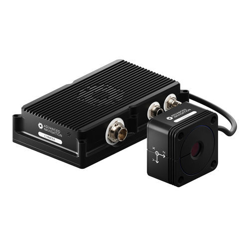
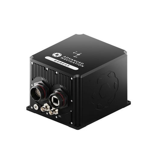
Inside an INS’ computational “black box,” a data fusion team manages the integration of these raw hardware readings. An INS relies on complex algorithms to fuse IMU data with aiding sensors, including GNSS, Doppler Velocity Logs (DVL), or odometers.
This creates a feedback loop to correct the IMU state and produce optimal, real-time estimates of a vehicle’s position, velocity, and orientation.
Surviving GNSS-Denied Environments
The true test of an inertial navigation sensor occurs when sensors are lost or jammed. Under these conditions, the system must rely purely on the integration of IMU data, a mode the industry refers to as ‘free inertial navigation’.
During free inertial navigation, the system utilizes INS mechanization to output high-rate data. The duration the vehicle can operate safely in this mode is therefore strictly dictated by the quality of the sensor and the accuracy of bias estimates calculated prior to entering the outage.
Unbounded Errors and Schuler Oscillations
Even factory calibrated units contain small residual biases that can shift every time a device is powered on. Understanding how this bias translates to navigation performance is vital.
Gyroscope Bias
In free inertial navigation, uncorrected gyroscope bias leads to unbounded heading and position errors over time. Furthermore, a gyroscope’s Angular Random Walk (ARW) specification directly dictates the convergence time during stationary pointing applications.
Accelerometer Bias
Accelerometer errors behave differently. Bias in the accelerometer induces a phenomenon known as “Schuler oscillations,” which creates bounded position errors. The time period of these oscillations relies on the Earth’s radius and local gravity, and is approximately 84 minutes
Advanced Navigation’s Approach
Implementing initialization routines enables the filter to obtain the best possible bias estimates before entering free inertial navigation, and thereby provide optimal navigation performance for a given mission.
Advanced Navigation’s algorithm and engineering teams are continuously refining algorithm architectures to ensure optimal performance, even in the toughest missions. Through ongoing performance optimization initiatives, we ensure our filters intelligently estimate the vehicle’s global position, velocity, and attitude in real-time.
This commitment to continuous research and development ensures that our inertial navigation systems deliver reliable, full-state control even in the most demanding, GNSS-denied environments.