
#Product Trends
Line Trap (Wave Trap / Line Coupling Trap) for Power Line Carrier Communication (PLCC) systems
Line Trap
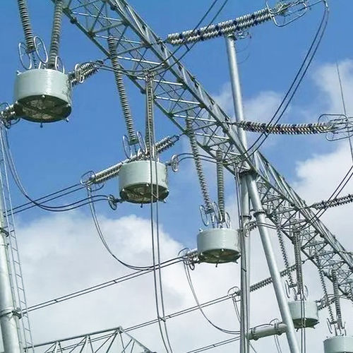
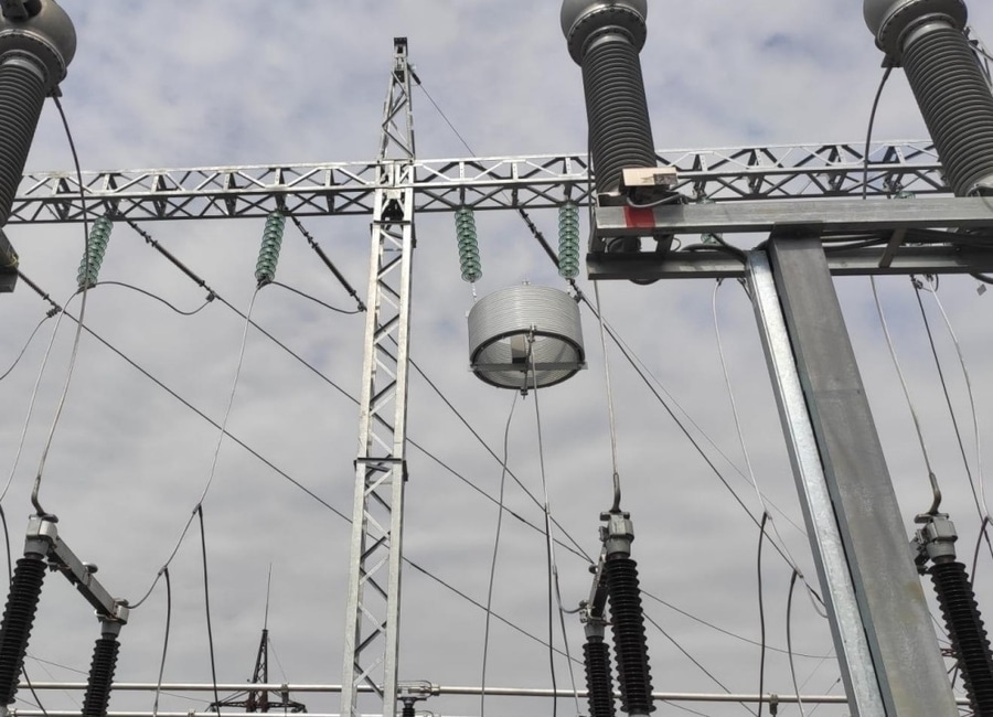
A Line Trap (also called a Wave Trap or Carrier Blocking Coil) is a high-voltage power system component used in Power Line Carrier Communication (PLCC) systems. It is installed in series with a transmission line to block high-frequency communication signals from entering unwanted parts of the power network while allowing 50/60 Hz power frequency current to pass normally.
Line traps are mainly used for:
·Substation communication
·Teleprotection
·SCADA data transmission
·Voice communication over transmission lines
1. Working Principle
A line trap acts as a high-frequency impedance device.
·At power frequency (50/60 Hz):
·It has very low impedance.
·Normal power transmission continues.
At carrier frequency (typically 30–500 kHz):
·It presents high impedance.
·It prevents communication signals from flowing beyond the intended section.
·The line trap creates a high-frequency blocking point while maintaining safe operation of the transmission system.
2. Main Construction
Main Coil (Main Reactor)
·Heavy aluminum or copper conductor
·Carries full transmission line current
·Provides inductive impedance
Tuning Unit
·Capacitors and inductors connected with the main coil
·Tunes the trap to the desired carrier frequency range
Protective Device
·Surge arrester installed across the tuning circuit
·Protects against lightning and switching surges
Mechanical Structure
·Aluminum alloy frame
·Insulating supports
·Designed for outdoor EHV installation
3. Types of Line Traps
A.) Broadband Line Trap
Features:
·Covers a wide carrier frequency range
·Simple tuning design
·Common in modern PLCC systems
Applications:
·Transmission networks
·Multi-channel communication systems
B.) Narrowband Line Trap
Features:
·Designed for a specific carrier frequency
·Higher impedance at selected frequency
Applications:
·Dedicated communication channels
C.) Single Frequency Tuned Trap
Features:
·Optimized for one carrier frequency
·High blocking efficiency
D.) Double Frequency Tuned Trap
Features:
·Blocks two carrier frequencies
·Used where multiple communication channels exist
4. Installation Location
Line traps are normally installed:
·On transmission line conductors
·Between the busbar and line disconnect switch
·Above or beside HV circuit breakers
Typical voltage levels:
·66 kV Distribution transmission
·110 kV Sub-transmission
·220 kV High-voltage transmission
·330 kV EHV transmission
·500 kV Long-distance transmission
·765 kV UHV transmission
5. Electrical Characteristics
·Rated voltage: 66 kV – 765 kV
·Frequency: 50/60 Hz power + carrier frequency
·Rated current: 400 A – 5000 A
·Short-time current: Up to 63 kA
·Carrier frequency: 30–500 kHz
·Installation: Outdoor
·Cooling: Natural air cooling
6. Advantages
·Reliable communication: Maintains PLCC channels
·Low power loss: Minimal impedance at 50/60 Hz
·High fault withstand: Designed for transmission faults
·Long service life: Passive equipment with low maintenance
·Improves protection speed: Enables teleprotection schemes
7. Applications
Power Line Carrier Communication (PLCC)
Used for:
·Relay protection signals
·Remote tripping
·Inter-substation communication
Teleprotection
Provides:
·Distance protection signaling
·Permissive trip signals
·Blocking signals
·Grid Monitoring
Supports:
·Supervisory control
·Operational communication
Line Trap summary:
A Line Trap is a tuned high-frequency blocking device installed on HV transmission lines to enable Power Line Carrier Communication (PLCC). It allows normal 50/60 Hz power transmission while preventing carrier communication signals from escaping into other parts of the electrical network. It is an essential component in EHV/UHV substations for protection, control, and communication systems.