#Product Trends
Rules for Actuator and Guide Alignment in Linear Motion Systems
Following a few simple guidelines for designing linear motion systems can improve system performance and actuator life.
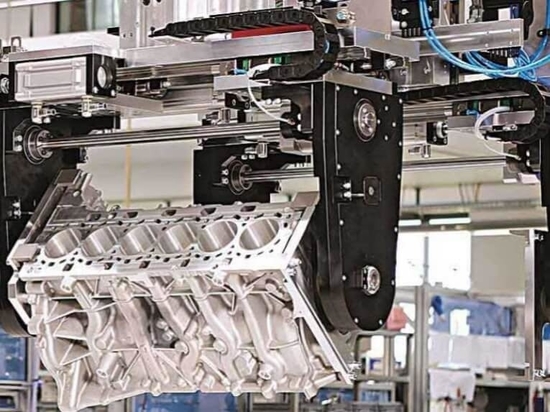
Many automated machines rely on linear guidance components, such as profiled rail, round rail or other rolling or sliding bearing structures, to guide and support the moving elements of equipment. Additionally, many times these moving elements are driven by some type of linear actuator device.
One of the most common issues in linear systems of any kind is misalignment. Misalignment can lead to a host of problems such as inconsistent linear motion results, shortened life of the linear bearing system, premature wear or failure of the actuator system, and erratic motion such as speed variation or wobbling.
However, there are some common ways to enhance overall system performance by optimizing the alignment of the linear guide and actuator.
Actuators and guides
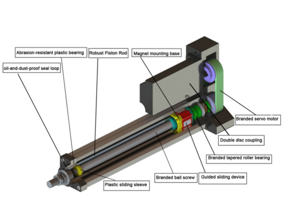
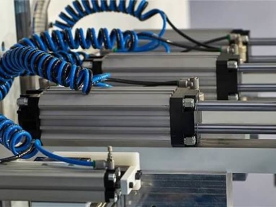
While there are a number of ways to impart motion to a guided machine member, some of the most common fall into two categories. The first is rod-style actuators. Rod-style actuators can be either fluid powered, such as hydraulic or pneumatic, or electric such as a lead screws or ball screws.
The second is rodless actuators. These, too, can be either fluid powered or electric via a lead screw, ball screw, belt or linear motor. Both styles of actuators find application in guided systems. However, each has subtle differences in how it is best employed to maximize system performance and life.
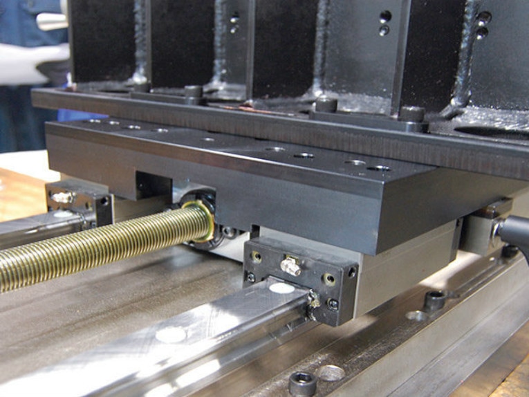
The guide elements themselves, whether profiled rail, round rail or other rolling or sliding systems, must be properly sized and selected during the design phase and installed following the manufacturer’s recommendations, paying particular attention to the process of alignment. Doing so assures that the performance of the selected guidance system is maximized for the particular application.
Perpendicularity of joined elements
There are two variables that affect perpendicularity when mounting linear actuators.
1. In an X-Y-Z system, is the Z-axis mounted perpendicular to the Y-axis? Misalignment in this plane will apply an unfavorable bending moment on the Y-axis actuator’s bearing system in any or all possible axes.
2. In a gantry system where two actuators are required to move simultaneously in the X- or Y-axis, are they moving simultaneously? Misalignment or inadequate servo performance will apply an undesirable bending moment in the Mz-axis to the bearing system.
Actual tolerances related to alignment recommendations and mounting depend on the specific actuator manufacturer as well as the bearing type. However, a general rule of thumb is to consider the bearing system type. High performance bearing types such as profile rail systems tend to be quite rigid and alignment is more critical. Medium performance systems using rollers or wheels often have clearances that offer some forgiveness in alignment. Plain bearing or sliding systems often have greater clearance and may be even more forgiving.
When installing linear actuator mounting systems there are a number of measurement tools available to help assure proper alignment ranging from gauges to laser systems. Whatever tools are used, always create one axis as a reference for the X-Y and Z planes and mount the other devices with respect to the reference axis. Doing so will help to get the maximum performance and longest life from your actuator system.