#Product Trends
Inside an Electric Linear Actuator
Major Components, Power Delivery and Stroke Travel.
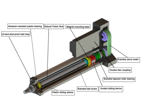
MAJOR COMPONENTS
This particular actuator is powered by a 12VDC brushed motor. It comes with the built-in end of travel limit switches to prevent overextension and retraction, a standard feature for our products. Other main components will be the gearbox, lead-screw and acme drive nut which also engages the limit switches once it reaches a certain position. The above picture shows the PA-14 in the middle of its stroke travel, meaning it can retract or extend until it reaches the limit switches.
POWER DELIVERY
A linear actuator by definition is an object that will move objects in a linear direction. Rotational motion is first generated by the electric motor, often in the thousandths of revolutions per minute.
This high-speed rotational motion is then reduced by the gearbox to increase the torque that will then be used to turn the lead-screw. Gearboxes often have a reduction ratio such as “100:1” which means for every 100 rotations of the motor, there will be 1 rotation on the final gear of the gearbox which is connected to the lead-screw.
The lead-screw then turns which results in linear motion of the acme drive nut. This is very similar to driving a screw into a piece of wood. However, instead of the screw moving towards the fixed piece of wood, it is the screw that is fixed and therefore the wood will be moving towards or away from the screw. Lead-screws come with a TPI specification, meaning turns per inch. For example, a TPI of 15 will mean for every 15 turns of the lead-screw, the connecting drive nut will move an inch.
The motor speed, gear reduction, and lead-screw TPI determine the final speed of the linear actuator. Our actuators have various force options per model. Those models typically have the same motor but the gear reduction and TPI changes. The rule of thumb is by reducing the speed, the force increases, and vice versa.
STROKE TRAVEL
One of the most convenient additions to a linear actuator is the built-in end of travel limit switches. Essentially this prevents the actuator from reaching the physical movement limits of the housing which will likely cause the motor to burn out. It also allows for a smoother stopping motion once the end of travel is reached.
The system employed for these limit switches is very simple and robust. The electricity from your power supply essentially goes from the input connector of the actuator to the motor, to the limit switches before it completes the circuit back to the connector as shown in the diagram below.
The limit switches break the path of travel of the electricity once it is touched by the drive nut. Now because of the unidirectional diode on each limit switch, electricity is only allowed to flow through in one direction. For example, the direction of electricity required to extend the actuator will be stopped by the extended limit switch and its diode.
However, the diode will allow the opposite direction of electricity which will be required to retract the actuator. Once the drive screw has retracted and is no longer touching the extended limit switch, then the electricity goes through the limit switch again allowing movement in both directions.