#Product Trends
What is a split bridge system and how does it differ from a gantry?
The Guide of how to avoid stacking errors.
Multi-axis linear systems come in a variety of designs, with Cartesian, gantry, and XY tables being some of the most common types. While these designs simplify construction and can provide space savings, they also introduce “stacking” errors — the compounding of errors from each axis, which manifests at the work piece or tool point. Mounting axes to one another also creates cantilevered loads and Abbé errors — angular errors that are amplified as the point of interest (work piece or tool point) moves farther from the source of the error. But one multi-axis configuration — the split bridge system — provides a solution for high-precision tasks that require multiple axes of motion while minimizing stacking errors.
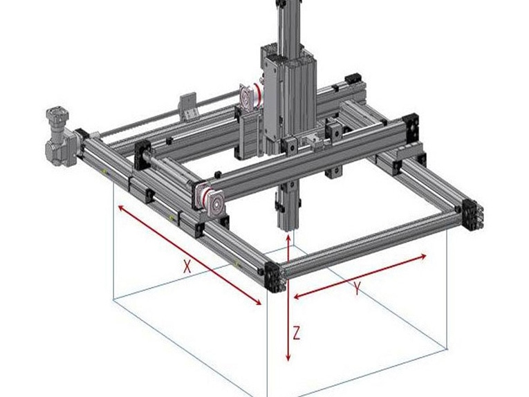
Split bridge systems provide two, three, or more axes of motion using a cross, or bridge, axis that spans the base and supports at least one of the axes. While this setup is similar to a traditional gantry, there are some notable differences. To start, a traditional gantry system uses two X, or base, axes with a Y axis that spans across them and — in most applications — a Z (vertical) axis mounted to the Y axis. The gantry design provides very long travel lengths with good load capacity and high rigidity, since roll moments on the X axis are eliminated and yaw moments can be minimized. But if the parallel X axes aren’t synchronized, racking, or skewing of the axes can occur, which will produce errors in the Y and Z axis positions.
A split bridge system avoids these issues by using a static member, or fixed bridge, to span the base axis or axes. The base axes — whether a single axis, an XY table, or a two-axis planar gantry — are mounted to a machined surface (typically steel or granite, although machined aluminum is sometimes used) for flatness and rigidity. The Z, or vertical, axis is mounted to the bridge, independent of the base axes. And in some cases both Y and Z axes are mounted to the bridge, making them both independent of the X axis. The axes mounted to the bridge are typically high-precision stages, like the base axes, although more traditional linear systems can also be used, depending on the application requirements.
One of the primary reasons for using a split bridge system is so a part or sample can be moved into a very precise position with the base axes, and then a process such as scanning, probing, or drilling can be done by the axis (or axes) mounted on the bridge.


