#Industry News
Linear Motion a Lifeline in Medicine
Specific Design and Operational Challenges in Medical and Clean-room applications.
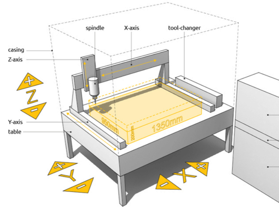
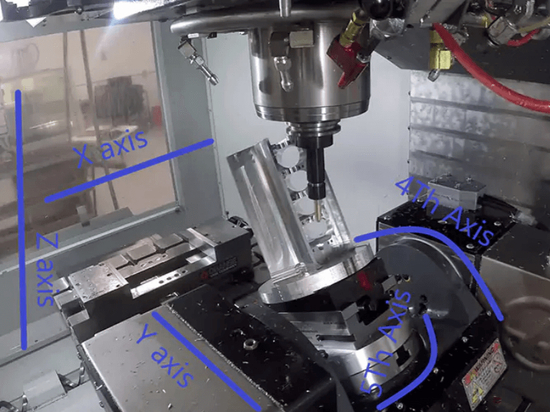
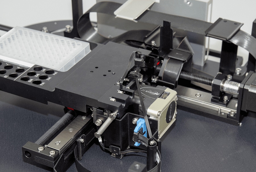
Linear Motion XYZ Stage for Sample Positioning
Life science, medical and biomedical equipment manufacturers must constantly pursue improvements in advanced technology, workflows and processes to pursue competitive pressures and market growth. But progress cannot only focus on expanding success; it must also ensure precision, reliability, functionality during operation—the prevention of in-use failures.
Neglecting improvements and safeguards in one seemingly minor component of in-process linear motion systems can generate consequences ranging from inconvenient to catastrophic. Manufacturers, as well as users, must remain vigilant.
With the proper focus, next-generation linear motion systems can be specified, designed, installed and maintained to advance and ensure the benefits of life science, medical and biomedical equipment in vital and even lifesaving applications.
Consequences
Because reliable linear motion is an operational necessity, equipment manufacturers and equipment users must monitor even relatively rare failure risks in linear motion components or systems throughout the process. This concern includes equipment ranging from DNA sequencing to bioprinting to atomic force microscopes (AFMs).
The stakes are enormous.
Failure of a single part or system can cost equipment users hundreds of thousands of dollars for even a relatively short-duration downtime event. Depending on location, severity and response time for repair or replacement, costs could mount to a great deal more.
The personnel safety risk is another paramount concern. While rare, design flaws or failure to follow operational safeguards can lead to anything from pinch points to runaway stages and cause damages from crushing injuries to electrical shock.
Specification and Design
Linear motion manufacturing facility be fully ISO-certified to ensure consistency in all its key processes. In addition, meticulous prototype builds help uncover steps that are key to maintaining the performance and the reliability of the finished motion component or system. Missing or not correctly performing any of many small, crucial steps in assembly or testing could ultimately lead to a failed system in the field.
Many manufacturers also establish targets that translate into many years of reliable service before an equipment upgrade. It is therefore important to properly calculate component service life. Because duty cycles may vary from application to application, service life is stated in kilometers traveled for many linear motion components. The linear motion maker must then translate that calculation into various decisions about the product.
For example, one widely-used cable specifies more than 10 million flex cycles if a 50-mm or greater bend radius is maintained. But, if the bend radius is not correctly sized, particulates falling from the cable or stress on the cable tracks or connectors could conceivably cause early failure in the process (especially where maintenance schedules are not strictly observed).
Consider Customization
Off-the-shelf parts play a critical role in many equipment assemblies. One concern, for example, is that a stock linear motion stage element may not have been designed and constructed to work with the precise combination of other components and structures that the supplier is assembling. Unexpected incompatibilities may arise.
The question is: Will a manufacturer catch issues during its routine design, quality control and inspection protocols? Probably. But not certainly.
Often, only customized offerings can meet the objectives of specific performance and design requirements. They allow the manufacturer to focus on the design aspects of the stage that the application requires, specifically tailoring factors from speed to acceleration to stability. They can even reduce cost by eliminating unneeded features that come standard with an off-the-shelf stage. And they ensure an integrated solution without hidden incompatibilities.
Suppliers should look for true “spec-sheet-to-prototype-build” control of their order from the linear motion manufacturer. Such intelligent customization is vital to anticipating and eliminating product shortcomings, avoiding roadblocks in integration and preventing failures throughout.
Specify products with the precise size, shape, coating or material the job demands. And insist on solutions that meet the unique targets for accuracy, speed, flatness, preloading (to increase stiffness by eliminating internal clearances), service life, maintenance levels and price.
Sometimes, more innovative materials may also help reduce risks in specific custom designs. For example, carbon fiber construction can optimize structural strength, stiffness and stability (despite its reduced weight and thickness). At the same time, ceramic bearings may be a viable solution for specific lubrication issues.
Handle With Care
Once a linear motion component destined for a specific application arrives on the equipment maker’s floor, other risks can arise.
Linear motion manufacturers may be called in to solve a host of problems arising at this intermediate stage. For example, a linear motor may suffer a binding problem, where the coil traveling inside the motor track is rubbing against the track in its travel. This might be caused by a handling issue due to jarring that slightly shifts the coil or the track out of alignment. It is possible the saddle—the moving stage segment—may get bumped and suffer distortion. In building the larger tool, screws that are too long may be added, pushing through one linear motion plate into another, causing scratches and the risk of unpredictable forces during operation. It also is possible a coil may be unscrewed from its mounting to allow access to run an additional cable, then re-screwed incorrectly.
Such mishaps run risks ranging from a slight degradation of performance in the process to burnt-out motors and major downtime events. Surface preparation also merits close attention. Tolerances must match in all particulars.
In some cases, a manufacturer building tools for these processes may source a linear motion component constructed for flatness of travel, say 0.0005 in. But the toolmaker then bolts that component down to a larger assembly with a flatness of only 0.005 in. The consequent twisting of the stage may be almost imperceptible. For example, this may cause binding of the bearings resulting in premature wearing of the bearings, additional forces on the ball screw or higher power requirements from linear motors resulting in excessive overheating and potential failure.
Get Grounded
Ensuring that all components in the linear motion system have proper electrical grounding is another precaution that manufacturers can undertake to prevent a future problem. Such an oversight might result in electrical shock risks for operators. But it can also have an impact on system performance.
A ground loop in the system that feeds back through the ground path could induce false readings in the encoder so that a component only travels 1 mm, but the controller registers travel of 100 mm. If the oversight is missed, for example, positional accuracy may result in errors in the readings of the instruments leading to inaccurate analysis.
Transport and Installation
The relatively low resistance of linear motion systems to impact loading was discussed earlier. The points of most significant risk naturally occur in three periods:
1. During transport from linear motion supplier to equipment tool maker;
2. During arrival and incorporation of the system into the equipment tool;
3. During transport of the finished equipment assembly to the process floor and installation.
A reliable, experienced linear motion supplier can significantly decrease the chance of shock damage during the first phase. Supplier experts can ascertain manufacturing space constraints early, so they do not design a stage that is too large or too heavy to be easily assembled in a cleanroom or manufacturing floor. They can also plan transport equipment usage (cranes, dollies, etc.) so that the stage can be safely transported from crate to tool, minimizing the risk of injury to onsite personnel, as well as the chance of damaging impacts.
Finally, during installation, the linear motion system or the relevant portion of the tool can be equipped with the necessary passive isolation measures (such as elastomer feet or pads) or active isolation dampers (sensor-adjusted airbag systems) to reduce the chance of excessive shock or vibration during subsequent operations.
In the Clean Room
For both the first and second phases, the linear motion supplier should follow best practices in constructing transport crates and bagging systems. For example, one leading supplier envelops the system in two bags, one applied within the nitrogen atmosphere and the second in a cleanroom, for transport. They then provide special rigging and carts for delicate transport transfers.
In the third phase, if the system will be placed on the tool assembly from above, the tool makers’ crane may suffice. However, if a more challenging sideload maneuver is necessary, the supplier provides a specialized chamber crate, which can be bolted to the side of the tool until mounting is accomplished.
Lubrication
Although linear motion systems usually run cycle after cycle without trouble or extra attention, a small amount of regular maintenance is always critical. Here there are three keys to effective maintenance: lubrication, lubrication and lubrication.
Every linear motion system supplier ships their product with a specified relubrication service cycle. Yet, human nature being what it is, many problems can be traced to simple failures to follow that recommended cycle. Without necessary lubrication, friction stresses mount and eventually cause extremely undesirable events—such as shutdowns or motor burnouts.
Other lubrication issues include premature failure of the bearings resulting in reductions in performance such as straightness, flatness, pitch, roll and yaw.
It is important to use only the correct grease on each machine. Take great care never to mix incompatible oils or greases. This includes using different greases when servicing a machine from one cycle to the next. This will change the required viscosity, often resulting in the buildup of a gummy, cement-like material that is the last thing to desire in delicate equipment. If the material also includes particulates from an over-flexed cable, a cable carrier or even elsewhere, usually rail failure will soon result.
Performance Roadmap
In response to demands from equipment manufacturers, linear motion equipment makers are continually working to push the envelope in performance. But first, they must ensure that any improvements do not inadvertently increase the risk of linear motion failures.
A good linear motion supplier will supply a “performance roadmap” highlighting elements of the system that can be designed not just for current requirements but with the performance capacity for next-generation use. This commitment is especially critical in the manufacture of advanced life science, medical and biomedical technology.
Linear motion process systems may not be the most prominent elements in most advanced technology equipment, and nor are they typically a top-of-mind concern for most users. But their failure can have severe consequences for all involved. Fortunately, proper attention to design, installation, operation and maintenance can ensure linear motion systems play a vital role in the continuing critical—and perhaps even lifesaving—successful operation of the most advanced life science, medical and biomedical equipment.