#Industry News
Explosion Proof Performance of Temperature Humidity Test Chamber
Explosion Proof Performance of Temperature Humidity Test Chamber
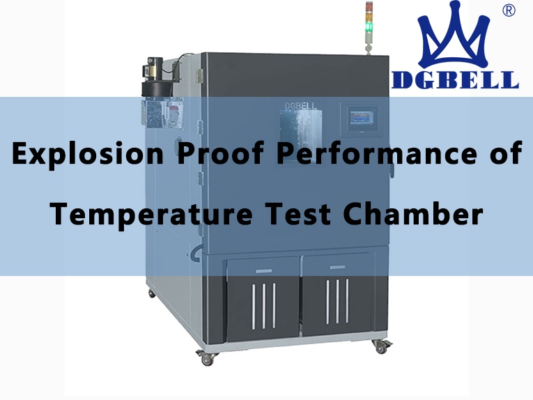
Environmental test equipment mainly simulates a series of natural conditions such as high and low temperature, damp heat, low pressure, sand and dust, and has high requirements for simulation accuracy. With the development of the industry. More and more customers need to put forward explosion-proof requirements for equipment while realizing the above environmental simulation. So as to adapt to a wider range of test samples. For explosion-proof, the concentration of combustible gas in the chamber shall be detected during the simulation test. When abnormalities are found, the test chamber shall take measures to reduce the concentration of combustible gas and avoid accidents such as combustion and explosion. Once an explosion occurs, the strength structure and protective measures of the test chamber are particularly important. Proper protection can reduce economic property losses and avoid casualties.
1.Control of Chamber
Explosion is caused by violent chemical reactions such as combustion. In order to prevent the combustion reaction of the sample in the high and low temperature humidity test chamber during the test. At the initial stage when a small amount of combustible gas is detected in the box, the action of introducing fresh air can be designed in the control of high and low temperature damp heat test box, and the concentration of combustible gas in the box can be kept within the safe range by introducing fresh air from the outside. In case of serious situations such as open fire and explosion in the box, the temperature in the box will rise sharply. At this time, fire extinguishing action should be designed in the control of the test box to control and extinguish the fire in the test box in time and prevent the open fire and explosion from spreading outside the test box. Avoid causing damage to surrounding equipment, property and casualties.
When the combustible gas detection device of the test chamber detects that the combustible gas concentration in the chamber reaches 400ppm, the inlet and exhaust air valves are opened. The ventilation and exhaust fan starts to operate at the same time, introduce fresh air from the outside into the equipment, and dilute the combustible gas concentration until the combustible gas concentration returns to below 400ppm; After the fresh air is continuously introduced for a period of time (the duration can be set by the external timer), the air exchange device stops working, and the test chamber does not stop during this process.
When the concentration of combustible gas in the test chamber rises to 1000ppm. The ventilation device continues to work, introduces fresh air and dilutes the concentration of combustible gas. In this process, the test chamber stops working. However, the safety explosion-proof system works normally.
If the concentration of combustible gas continues to be above 1000ppm, it cannot be reduced in time, and the temperature in the chamber rises sharply, resulting in combustion or explosion in the test chamber, and the ventilation system is closed at this time. The CO2 fire-fighting device is automatically turned on, and the high-pressure CO2 is instantly injected into the test box through the nozzle in the test box, put out the open fire in the test box, and reduce the temperature in the test box. In this process, the test chamber is shut down and does not work, and the safety and explosion-proof system of the test chamber works normally to prevent combustion and explosion from causing greater damage to the box of the test chamber.
2.Electrical Design of Chamber
In order to realize the explosion-proof early warning detection of high and low temperature damp heat test chamber, control the concentration of combustible gas in the test chamber and automatically extinguish the fire after combustion and explosion, some special designs are needed in the electrical aspect.
2.1 Combustible Gas Sensor
A combustible gas concentration detection sensor is installed at the front end of the high and low temperature damp heat test chamber. The sensor adopts a pump suction structure. Sample and suck the gas from the test chamber for detection. The sampling port is installed at the air outlet of the circulating air in the box. The combustible gas sensor panel can set and display two alarm points. When the detected combustible gas concentration in the box exceeds the set alarm point, the combustible gas sensor will give warning or danger alarm signal and output corresponding open circuit signal through its own output terminal. After the system PLC detects that the corresponding Di input signal is disconnected, it makes the corresponding do output action, so as to control the start of safety protection devices such as ventilation device and CO2 fire extinguishing system.
2.2 Heater
In order to avoid fire, ordinary nickel chromium wire heater cannot be used in the explosion-proof box, but fin armored electric heater must be used, and the armored pipe and fin are made of stainless steel. The encapsulated heater will neither produce open fire nor cause secondary faults such as short circuit due to external forces such as explosion.
2.3 Ventilation Damper
Ventilation fans, ventilation valves and dampers are set on both sides of the door body Ф The 100 air duct is connected to the chamber, and a check valve plate is set at the connection with the wall of the test chamber. When the air is not changed, there is no gas exchange between the box and the outside. The ventilation valve and the ventilation fan are installed on the outside of the test chamber and equipped with a protective cover. The ventilation capacity of the ventilator shall not be less than 5m / min.
2.4 Automatic jet CO2 Fire Fighting Device
In case of fire and explosion, the temperature in the high and low temperature damp heat test chamber will rise sharply. This abnormal temperature change can be detected by a special temperature sensor, and the abnormal temperature signal is transmitted to the control system of the test chamber. The system injects CO2 by opening the electric valve. The high-pressure CO2 fire tank and electric valve body are installed on the outer wall of the box, and the nozzle is installed in the box. In addition, “manual switch” and “cancel switch” are set at the operation display panel. When the operator finds that there are abnormal conditions in the box that require the action of CO2 fire fighting device, he can manually press the manual switch. This manual switch is used in conjunction with the external delay timer to prevent misoperation. The cancel switch can be pressed within the delay time set by the user to cancel the CO2 injection action. It is worth noting that. If the safety protection door is open, CO2 fire fighting will not work, so as to prevent personnel from being injured by high-pressure CO2.
2.5 Temperature Anomaly Detection
Two temperature sensors that can move anywhere in the box are equipped to detect the surface temperature of the sample. When the surface temperature of the sample is abnormal and higher than the preset temperature, the red alarm light of the equipment and the over temperature light in the box will light up at the same time, and the equipment will stop running and cut off the sample power through the test power supply terminal.
2.6 Emergency Stop Switch
When the operator finds any abnormality in the box, immediately press the emergency stop switch, stop the operation of the box, and cut off the secondary power supply of the test box through the AC contactor, but the safety system (ventilation, CO injection, etc.) is not affected and works normally.
2.7 Display Panel of Safety Operation Device
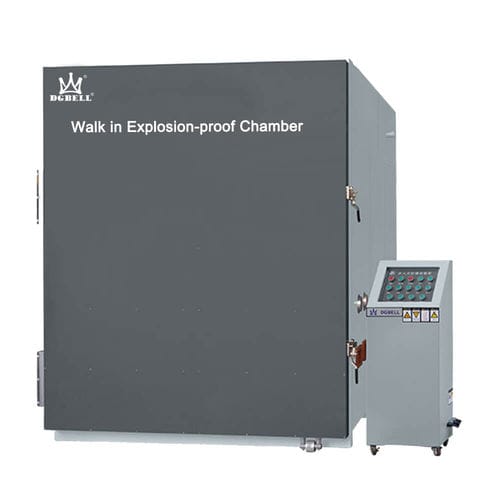
It is installed at the most easily operated position of the equipment, that is, the right position of the front of the box. The switch of ventilation device, manual automatic switching of CO2 fire fighting device, emergency stop switch, gas alarm lamp and abnormal temperature display lamp in the box are installed here.
2.8 UPS Uninterruptible Power Supply
It is used to supply power to the gas alarm circuit, ventilation device, CO2 fire fighting device, temperature indication alarm circuit and operation display board of safety device in case of power failure or when the leakage circuit breaker and automatic circuit breaker of the test box box act, so as to ensure the normal operation of the safety system in case of power failure or explosion.
3.Structure of Chamber
3.1 Chamber Reinforcement
100mm channel steel is used to strengthen the protection on the outside of the box to prevent serious deformation and damage caused by huge impact on the box of the test box, fire diffusion and accidental injury caused by hard objects. The cover plate is divided into small blocks to avoid the channel steel position, which is convenient for the daily maintenance of the test box in the disassembly and assembly room.
3.2 Safety Protection Door
In addition to the large door with observation window outside the box of the test box, reinforced safety protection door shall also be installed. Pay attention not to block the controller and observation window of the test box. The protective door is also equipped with a limit switch for door opening detection. When the safety protective door is opened, the equipment box stops running; The test chamber can only operate when the protective door is closed and the limit switch is closed.
3.3 Observation Window
The design size of the observation window should not be too large. It should be round. The outer ring and the door of the test chamber can be fixed with double-layer stainless steel fasteners. In terms of glass material, toughened explosion-proof glass should be used, and a protective net cover should be installed outside the glass for protection to prevent glass fragments from hurting people during explosion.
3.4 Lead Hole
In addition to the thermal insulation rubber plug, the lead hole shall also be equipped with a threaded protective screw cover with a small hole drilled on the screw cover. Embedded protective sleeve for threading. When the pressure in the box rises sharply, the screw cap can prevent the rubber plug from shooting out and hurting people.
3.5 Installation Site
In order to avoid the pressure rise around the test chamber when the high and low temperature damp heat test chamber releases pressure. The installation site of the test chamber shall be spacious and there shall be no obstacles around the test chamber. In order to prevent fire in the laboratory and secondary loss caused by pressure relief, a certain distance shall be reserved between the top of the test box and the roof of the laboratory.


