
#Industry News
Engineering Design and Technical Specifications for Centralized Lab Gas Piping Systems
Engineering Design and Technical Specifications for Centralized Lab Gas Piping Systems
Introduction
In modern analytical laboratories, research and development facilities, and high-tech manufacturing cleanrooms, the purity, safety, and reliability of gas supplies are non-negotiable. Traditional methods relying on standalone compressed gas cylinders scattered across individual workstations present significant safety hazards, workspace clutter, and inconsistent delivery pressures. This has driven the industry-wide transition toward centralized lab gas piping systems.
Centralized gas supply systems consolidate gas sources—such as gas cylinders, dewars, and generator farms—into a dedicated, well-ventilated exterior storage area or gas room. From this hub, high-purity gases are distributed through an intricate network of specialized piping to precise points of use (PoU). However, designing and installing such a network is a high-stakes engineering endeavor. A minor design flaw, incorrect material selection, or improper pressure regulation can compromise sensitive analytical results, damage expensive instrumentation, or, worst of all, trigger catastrophic safety incidents.
For EPC (Engineering, Procurement, and Construction) contractors, laboratory engineers, and technical directors, mastering lab gas piping design standards is essential. This technical guide explores the rigorous engineering principles, material science, and safety frameworks required to design world-class centralized laboratory gas piping systems.
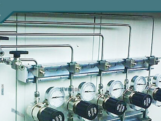
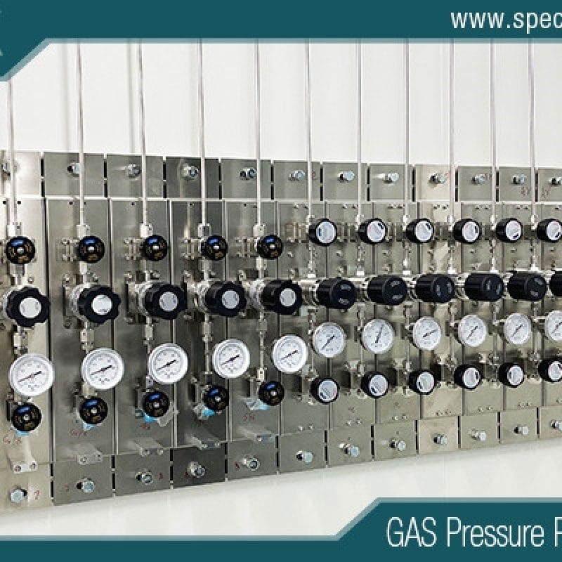
high pressure hydrogen gas manifold system
Key Design & Safety Standards
Compliance with international and regional codes forms the bedrock of any reputable centralized gas engineering project. Designing without strict adherence to these standards not only invites regulatory penalties but introduces unacceptable operational risks.
1. NFPA 55: Standard for the Storage, Use, and Handling of Compressed Gases and Cryogenic Fluids in Portable and Stationary Containers, Cylinders, and Tanks
NFPA 55 is arguably the most critical standard governing lab gas systems. It dictates requirements for fire safety, separation distances, ventilation rates for gas storage rooms, and the structural integrity of gas cabinets and manifolds. For interior piping, NFPA 55 outlines restrictions on material types based on gas hazard categories (e.g., flammable, oxidizing, toxic, or corrosive gases).
2. Compressed Gas Association (CGA) Publications
CGA standards provide granular technical guidance on connection types, valve specifications, and cylinder handling. Key publications include:
CGA V-1: Standard for Compressed Gas Cylinder Valve Outlet and Inlet Connections (ensuring cross-connection prevention).
CGA G-4.1: Cleaning Equipment for Oxygen Service (vital for preventing combustion in oxygen-rich lines).
CGA P-1: Safe Handling of Compressed Gases in Containers.
3. OSHA (Occupational Safety and Health Administration) Regulations
OSHA standards (such as 29 CFR 1910.101 and 1910.103) mandate safe working conditions, proper employee training, emergency response protocols, and the use of certified equipment when handling hazardous chemicals and compressed gases.
4. ISO Standards
International Organization for Standardization guidelines, including ISO 11114 (compatibility of cylinder and valve materials with gas contents) and various ISO cleanroom standards, ensure that system components harmonize globally, facilitating seamless multinational compliance.
Material Selection for Lab Gas Pipelines
The integrity of a centralized gas network depends heavily on the metallurgical properties of the piping infrastructure. Unlike industrial plumbing, lab gas piping cannot use standard commercial-grade steel or copper without risking contamination, particulate shedding, and chemical degradation.
Why BA and EP 316L Stainless Steel Tubes Are Mandatory
For high-purity (HP) and ultra-high-purity (UHP) gases (purity levels from $99.999\%$ to $99.9999\%+$), BA/EP stainless steel tubes made from grade 316L are the undisputed gold standard.
Grade 316L Stainless Steel: The low carbon content ($0.03\%$ maximum) of 316L prevents carbide precipitation during orbital welding, ensuring that the weld zones remain corrosion-resistant and structurally sound. Furthermore, its molybdenum content enhances resistance to pitting and crevice corrosion, particularly when handling trace moisture or corrosive components.
Bright Annealed (BA) Tubing: BA tubes are annealed in a controlled, oxygen-free atmosphere furnace. This process yields a bright, smooth internal surface finish (typically with a surface roughness of $Ra \le 0.4\,\mu m$ or $15\,\mu in$). BA tubing is widely used for general analytical gases (e.g., helium, argon, nitrogen) where standard high purity is required.
Electropolished (EP) Tubing: For ultra-high-purity applications, semiconductor manufacturing, and extremely reactive or corrosive gases, EP tubing is mandatory. The internal surface undergoes an electrochemical smoothing process that strips away microscopic peaks and valleys, passivates the chromium oxide layer, and achieves an exceptionally smooth surface finish ($Ra \le 0.15\,\mu m$ or $6\,\mu in$). This ultra-low surface roughness minimizes dead zones, prevents gas molecule adsorption/desorption, and drastically reduces particle generation and dry-down time during purging.
Handling Different Gases: Inert vs. Reactive/Toxic Gases
Material selection must also account for the chemical nature of the gas being transported:
Inert Gases (Helium, Argon, Nitrogen): BA 316L stainless steel is typically sufficient. These gases do not react with pipe walls, but moisture and air ingress must be prevented to maintain purity.
Oxidizing Gases (Oxygen, Nitrous Oxide): All components—including pipes, fittings, regulators, and valves—must undergo specialized cleaning for oxygen service (degreased to remove all hydrocarbon traces) to eliminate fire and explosion hazards in accordance with CGA G-4.1.
Flammable Gases (Hydrogen, Acetylene, Methane): Piping systems require dedicated mechanical ventilation, flashback arrestors (for acetylene), and leak-proof welded connections. Copper piping is strictly prohibited for acetylene due to the risk of forming explosive copper acetylide compounds.
Corrosive and Toxic Gases (Ammonia, Chlorine, Hydrogen Chloride): EP 316L stainless steel is essential, often supplemented by specialized nickel alloys like Hastelloy for extreme environments. Systems must feature double-containment piping or be housed in dedicated exhausted gas cabinets.
System Layout & Pressure Management
A well-designed distribution layout balances optimal fluid dynamics with structural safety, minimizing pressure drops while maintaining precise delivery parameters at every instrument.
Main Pipeline Sizing and Pressure Drop Calculations
Designing a centralized gas system requires careful calculation of peak flow rates, simultaneous usage factors, and allowable pressure drops. If a pipeline is undersized, downstream instruments will experience pressure starvation when multiple users draw gas simultaneously.
The calculation of pressure drop ($\Delta P$) across the piping network utilizes fluid dynamics principles adapted for compressible gases, such as the Darcy-Weisbach equation or simplified isothermal flow formulas:
$$\Delta P = f \cdot \frac{L}{D} \cdot \frac{\rho v^2}{2}$$
Where:
$f$ = Darcy friction factor (dependent on Reynolds number and pipe roughness)
$L$ = Equivalent length of the pipe (including fittings, valves, and bends)
$D$ = Internal diameter of the tube
$v$ = Gas velocity
Design Best Practices: Gas velocities within the main headers should generally be restricted to prevent flow-induced vibration and excessive pressure loss (typically kept below $15$ to $20\,m/s$). Standard outer diameters (OD) for laboratory lines commonly range from $1/4$ inch to $1$ inch, depending on distance and volumetric demand.
Gas Pressure Regulation Stages
To ensure safety and stability, centralized gas systems utilize a multi-stage pressure reduction philosophy:
Primary Pressure Control (Source Stage): Located at the gas source manifold or gas cabinet. This stage steps down the high cylinder pressure (up to $150$ to $200\,bar$) to an intermediate distribution pressure (typically $6$ to $10\,bar$). Many advanced manifolds feature automatic changeover regulators that seamlessly switch from an empty cylinder bank to a reserve bank without interrupting supply.
Secondary Pressure Control (Line Regulator Stage): Positioned upstream of secondary distribution branches or entering specific laboratory zones. This further reduces pressure to around $3$ to $5\,bar$, stabilizing the line against long-run friction losses.
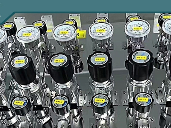
Point of Use (PoU) Control: Located directly at the workstation or instrument inlet (e.g., gas chromatographs or mass spectrometers). A high-precision diaphragm regulator and shut-off valve allow the end-user to fine-tune delivery pressure down to exact operational requirements (e.g., $1$ to $2\,bar$) right before the gas enters the analytical hardware.
Leak Detection and Alarm Systems
Even the most robustly engineered piping network is vulnerable to unexpected incidents. A comprehensive safety architecture must integrate active monitoring, automated containment, and emergency ventilation controls.
1. Gas Sensors and Detectors
Strategic placement of electrochemical, infrared, or catalytic bead gas sensors is mandatory. Sensors should be installed near potential leak sources:
Gas source cabinets and cylinder storage rooms.
Manifold connections and pressure regulator assemblies.
Underneath analytical workbenches utilizing toxic or flammable gases.
At ceiling levels for lighter-than-air gases (e.g., hydrogen) or near floor levels for heavier-than-air gases (e.g., argon, carbon dioxide).
2. Automatic Shut-Off Valves (ASVs)
Integrated safety systems tie gas sensors directly into Pneumatic Emergency Shut-Off Valves (ESVs) installed at the gas source. If a sensor detects gas concentrations exceeding pre-set safety thresholds (e.g., $20\%$ of the Lower Explosive Limit for flammables, or immediate danger levels for toxics), the system automatically triggers the solenoid valves to isolate the gas supply at the source cylinders, preventing continuous leakage into the facility.
3. Ventilation Interlocks
Gas rooms and enclosed gas cabinets must be equipped with mechanical exhaust ventilation systems tied to airflow switches and gas detectors. If ventilation airflow drops below required air-change rates, or if a gas leak is detected, an interlock system can simultaneously shut off incoming gas supply valves, activate visual/audible alarms, and trigger emergency exhaust fans to clear hazardous vapors safely to the exterior atmosphere.
UHP Single Stage Specialty Gas Pressure Regulator
Conclusion
Centralized gas engineering is far more than a simple plumbing task; it is a critical scientific infrastructure discipline that safeguards personnel, protects high-value analytical equipment, and ensures experimental repeatability. By adhering strictly to recognized global standards (such as NFPA 55 and CGA), selecting premium materials like BA/EP 316L stainless steel tubes, engineering precise pressure-drop-managed layouts, and integrating advanced safety interlocks, EPC contractors and laboratory managers can build future-proof facilities.
Investing in professional lab gas piping design standards and expert execution today lays the solid foundation for safety, efficiency, and cutting-edge research tomorrow.
For more about silane gas abatement system for semiconductor and CVD processes, you can pay a visit to Jewellok at https://www.specialtygasregulator.com/product-category/specialty-gas-cabinet/ for more info.