
#Industry News
Laboratory Gas Distribution System: Pressure Regulation and Gas Purity Control
Laboratory Gas Distribution System: Pressure Regulation and Gas Purity Control
Modern analytical laboratories rely heavily on a continuous, reliable, and ultra-pure supply of gases to operate sophisticated instrumentation such as Gas Chromatography (GC), Gas Chromatography-Mass Spectrometry (GC-MS), Inductively Coupled Plasma Mass Spectrometry (ICP-MS), and Fourier Transform Infrared Spectroscopy (FTIR). Carrier, combustion, and auxiliary gases—such as helium, hydrogen, nitrogen, zero air, and argon—must be delivered from their storage sources to the point of use (POU) with absolute integrity.
A well-designed laboratory gas distribution system eliminates the safety hazards associated with loose gas cylinders inside the laboratory while ensuring rigorous control over pressure regulation and gas purity. This article explores the core architectural components, engineering principles, contamination control strategies, and safety protocols governing modern laboratory gas supply systems.
pressure regulator vs pressure relief valve
1. System Architecture and Design Principles
A centralized laboratory gas distribution system typically transitions gas from bulk storage or high-pressure cylinder banks located outside or in a dedicated gas room to individual instruments across the laboratory. The architecture generally comprises three main zones:
The Source/Supply Zone: Cylinder manifolds, automatic changeover panels, or bulk cryogenic liquid dewars.
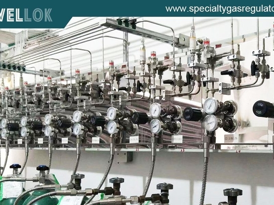
The Distribution Piping Network: High-purity stainless steel tubing, fittings, and valves routed through chases or ceilings.
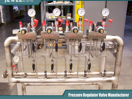
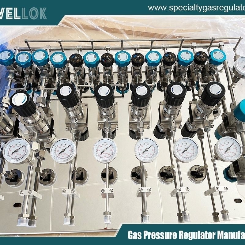
The Point-of-Use (POU) Zone: Dual-stage regulators, shut-off valves, flash arrestors, and purifiers located directly adjacent to analytical equipment.
Material Selection
The integrity of a gas distribution system is fundamentally tied to its metallurgy. For inert and carrier gases (helium, nitrogen, argon), 316L stainless steel is the industry standard due to its corrosion resistance and low outgassing rate.
Surface Finish: Tubing intended for high-purity applications (> 5.0 grade) undergoes mechanical polishing followed by chemical passivation and electropolishing (EP). Electropolishing removes micro-defects and smooths the inner surface (achieving an average roughness Ra≤10 \muin or0.25 \mum), minimizing active sites where moisture and hydrocarbons can adsorb.
Fittings and Connections: Component joints are ideally orbital-welded rather than threaded or compression-fitted wherever possible to eliminate dead legs and potential leak paths. Where mechanical fittings are necessary, high-integrity face-seal fittings (such as VCR-type fittings) with metal gaskets are utilized.
2. Pressure Regulation Mechanics
Precise pressure control is critical for maintaining stable flow rates, retention times, and detector baselines in analytical instruments. Fluctuations in supply pressure directly translate to analytical noise or baseline drift.
[High-Pressure Cylinder] ──> [First-Stage Regulator (Reduces to ~100-150 psi)]
│
▼
[Distribution Piping]
│
▼
[Point-of-Use Instrument] <── [Second-Stage Regulator (Reduces to 15-60 psi)]
Two-Stage Pressure Reduction
To achieve maximum stability, distribution systems employ a two-stage pressure regulation strategy:
Source/First-Stage Regulator: Attached directly to the manifold or cylinder regulator. It drops the high storage pressure (up to 2000–3000 psi for compressed gas cylinders) down to an intermediate distribution pressure (typically 100 to 150 psi). As the cylinder empties, its internal pressure drops; a first-stage regulator compensates for this supply pressure effect (SPE) to ensure the intermediate pressure remains relatively constant.
Point-of-Use (POU) / Second-Stage Regulator: Located at the laboratory bench or wall station, this regulator steps the intermediate pressure down to the exact working pressure required by the instrument (typically 15 to 60 psi). Because the inlet pressure to the second-stage regulator is constant (controlled by the first stage), the delivery pressure remains exceptionally stable, preventing drift caused by supply depletion.
Regulator Design Considerations
Diaphragm Material: Metal diaphragms (typically stainless steel or Hastelloy) are preferred over elastomer diaphragms (like Buna-N or Viton) in high-purity systems. Elastomers can absorb moisture and gases, later outgassing them into the stream and degrading purity.
Tied-Diaphragm Design: For toxic, corrosive, or reactive gases, tied-diaphragm regulators ensure positive mechanical retraction of the poppet when the handle is turned counter-clockwise, preventing valve sticking.
3. Gas Purity and Contamination Control
Even if a gas cylinder is certified as “Ultra-High Purity” (UHP, e.g., Grade 5.0 representing 99.999% purity), contaminants can enter the stream due to improper piping, inadequate purging, leaks, or outgassing. The primary contaminants of concern are moisture (H2O), oxygen (O2), and total hydrocarbons (THC).
Common Contamination Pathways
Atmospheric Ingress: Micro-leaks in threaded connections or poorly purged lines allow ambient air (O2, N2, H2O) to diffuse inward.
Desorption: Moisture trapped in micro-fissures or on internal pipe walls during installation slowly releases over time, poisoning sensitive detectors (like Mass Spectrometer quadrupoles or Electron Capture Detectors).
Outgassing: Contaminants trapped in elastomeric seals or regulator seats.
Purification and Trapping Technologies
To safeguard instrumentation, purifier traps are installed inline immediately upstream of the analytical instrument:
Moisture Traps (Molecular Sieves): Utilize synthetic zeolites to adsorb water vapor down to sub-part-per-billion (ppb) levels.
Oxygen Traps: Typically consist of active metal catalysts that chemically bind trace oxygen, protecting GC columns from oxidative degradation and bleeding.
Hydrocarbon Traps: Activated carbon or specialized adsorbents remove heavy organic molecules that cause ghost peaks and baseline rise during temperature-programmed runs.
Purging Protocols
Whenever a new cylinder is connected or maintenance is performed, ambient air is introduced into the system. To eliminate this air before gas reaches the instrument, rigorous purging procedures are mandated:
Pressure Cycling (Cycles of Pressurization and Venting): The system is pressurized with UHP inert gas (e.g., helium or nitrogen) to 100 psi and then vented down to near-atmospheric pressure repeatedly (typically 5 to 10 cycles). This dilution technique exponentially reduces residual atmospheric gas concentration.
Vacuum Purging: Utilizing a vacuum generator to evacuate lines prior to filling with UHP gas, which is especially effective for removing stubborn adsorbed moisture.
4. Safety Protocols and Leak Detection
Laboratory gas distribution systems involve high pressures, and in some cases, flammable gases (such as hydrogen for GC flame ionization detectors) or asphyxiants (such as helium and nitrogen). Robust safety design is non-negotiable.
Safety Engineering Controls
Pressure Relief Valves (PRVs): Installed downstream of regulators to protect piping and instruments from over-pressurization in the event of regulator failure.
Flashback Arrestors: Mandatory on hydrogen and fuel gas lines, preventing flame propagation backward into the distribution piping.
Excess Flow Valves (EFVs): Designed to automatically shut off gas flow if downstream piping is severed or experiences catastrophic rupture.
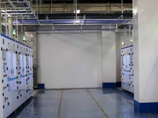
Ventilation and Gas Sensing: Dedicated gas rooms housing high-pressure cylinders must feature continuous mechanical ventilation and electrochemical or catalytic gas sensors tied to automated shut-off solenoid valves and building alarms.
Leak Testing
Before commissioning, any new gas distribution network must undergo rigorous pressure and leak testing. Standard procedures include:
Proof Pressure Testing: Pressurizing the system above normal operating pressure to verify structural integrity.
Helium Mass Spectrometer Leak Testing: The gold standard for ultra-pure systems, capable of detecting microscopic leak rates as low as 10-9std cm3/sec.
5. Maintenance, Validation, and Troubleshooting
A gas distribution system requires lifecycle management to maintain analytical reliability:
Routine Inspections: Periodic checks of regulator set-points, verification of cylinder changeover mechanisms, and inspection of flexible pigtails for wear or kinking.
Purph/Trap Replacement: Inline traps have finite capacities and must be replaced on a scheduled basis (or monitored via indicator windows/electronic sensors) before breakthrough occurs.
Analytical Correlation: Sudden baseline shifts, ghost peaks, shortened column lifetimes, or noisy detector baselines often serve as the first diagnostic indicator of distribution system contamination or pressure instability.
pressure regulator vs pressure relief valve
Conclusion
Laboratory gas distribution systems serve as the invisible backbone of modern analytical chemistry. By combining intelligent architectural design, electropolished 316L stainless steel metallurgy, precise two-stage pressure regulation, and aggressive inline purification, laboratories can achieve the high degree of gas purity and pressure stability required for ultra-trace level detection. Adherence to strict purging protocols and safety standards ensures both analytical reproducibility and laboratory personnel protection.
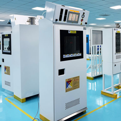
For more about why are gas cabinets required for toxic and corrosive laboratory gases, you can pay a visit to Jewellok at https://www.specialtygasregulator.com/product-category/specialty-gas-cabinet/ for more info.