#Product Trends
Busbar Clearance and Creepage: Why Spacing Decides Arc Safety in LV Panels
How IEC 60664-1 and IEC 61439 split the job, what changes with pollution degree and altitude, and why fabrication accuracy keeps the designed gap.
Busbar clearance and creepage distances decide whether a low-voltage switchboard survives a transient or slowly tracks toward failure. A new technical guide from PAYAPRESS explains how panel builders can size both correctly under IEC 61439 and IEC 60664-1.
Two distances, two failure modes
Clearance is the shortest path through air between live parts. It protects against flashover during switching or lightning surges and is sized from the rated impulse withstand voltage (Uimp). Creepage is the shortest path along an insulating surface. It protects against surface tracking, a slow process in which dust and moisture form a conductive film that carbonises the insulator over months or years. Passing one check does not satisfy the other.
Which standard does what
IEC 60664-1 is the insulation coordination method that supplies the spacing values for equipment up to 1,000 V AC or 1,500 V DC. IEC 61439-1 is the product standard for the finished assembly; its section 10.4 refers back to IEC 60664-1 rather than defining values of its own. For metal-enclosed switchgear above 1 kV, IEC 62271-200 applies instead.
A worked example
For a typical industrial switchboard with a rated insulation voltage of 1,000 V and overvoltage category III, Uimp is 8 kV, which corresponds to a minimum clearance of 8 mm up to 2,000 m altitude. Above that height the air gap is multiplied by a correction factor of 1.14 at 3,000 m, 1.29 at 4,000 m and 1.48 at 5,000 m. Creepage is not corrected for altitude, but it needs an input that clearance does not: the insulating material group defined by the comparative tracking index (CTI).
Pollution degree, the most misapplied input
The guide argues that most industrial panels should start from pollution degree 3 rather than 2, because conductive dust and condensation are normal on a factory floor. Moving from PD2 to PD3 can enlarge the required creepage path considerably at the same voltage. Ribs and grooves on insulators lengthen the surface path without enlarging the footprint.
From drawing to copper
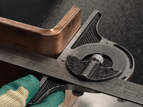
According to the article, the most frequent real cause of arcing is not a calculation error but a bar fabricated slightly off drawing and forced into place, leaving 5 mm where 8 mm was specified. Support spacing matters for the same reason: short-circuit forces can deflect a bar into the adjacent phase. Accurate cutting, punching and bending of busbars is therefore part of insulation design, not only of production.
The full guide, with comparison tables, the overvoltage category chain and an FAQ, is available on payapress.com.