#Industry News
#1 Reason for Retaining Ring Failure and How to Overcome It
Drills, saws, sanders, and grinders - what do all of these power tools have in common? Retaining rings keep them from falling apart.
Drills, saws, sanders, and grinders - what do all of these power tools have in common?
Retaining rings keep them from falling apart.
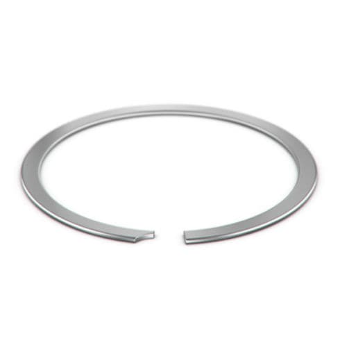
A retaining ring’s function is to hold components or assemblies in place. For a retaining ring in a power tool, this is no easy feat as it is regularly exposed to high axial and vibrational force. The retaining ring must maintain its integrity, despite the various types of forces acting against it.
Understanding why failure happens and how to prevent it is imperative. The consequences of retaining ring failure include safety concerns, repair costs, and even negative product reputation.
Several factors can accelerate retaining ring failure.
The most common method of failure occurs at the groove, not the ring. In fact, groove deformation accounts for 90% of retaining ring failures.
Groove Deformation Causes
Thrust Load
Groove deformation occurs when the bore or shaft’s yield strength is less than the ring’s yield strength. If the maximum allowable thrust load is exceeded, the ring can dish or compress the groove edge, causing deformation. The compromised groove wall allows for the ring to expand, twist, and ultimately pop out of the groove.
Choosing a stronger groove material as well as using a deeper groove are two ways to reduce your chances of ring failure if your application involves high thrust loads.
Impact Load
Impact loading can also be a cause of retaining ring failure. It must be considered in both housing and shaft rings. As an impact load is applied, the shock causes the diameter of the ring to expand/contract, depending on whether it is a housing or a shaft ring. This change in diameter causes the ring to expand/contract out of the groove. Similarly, cyclic loading and vibration can cause the ring to move out of the groove over time.
Increasing the cling (interference fit between the ring and the groove) or using a heavier cross-section will help increase the radial force against the groove. Using square-edged wire, such as a Constant Section Snap Ring, is also a viable solution.
If impact loading is anticipated, Smalley engineers recommend testing the ring in the application. Smalley provides Free Samples on all standard rings.
Groove Geometry Guidelines
Accounting for groove geometry is another crucial design consideration. The groove form, including groove depth, chamfers, radii, and edge margin, all impact retention capacity. In cases where the following guidelines aren’t met, the thrust load capacity can be reduced.
Groove Bottom
Ideally, the groove bottom should be flat so that the ring has the appropriate geometry for optimal cling. To allow for tooling capabilities or machining capabilities during the cutting of the groove, we have a recommended maximum groove radius.
The recommended groove corner radius for a retaining ring with a diameter of 1 in. and under is .005 in. maximum. For a retaining ring with a diameter larger than 1 in., it is .010 in. maximum.
If the radius on the groove bottom is too large, the ring may not engage properly and slip out of the groove.
Groove Corners
The corners of the groove should be as sharp as the manufacturing capabilities allow for. The sharper corner allows for more contact with the ring and a rounded corner can contribute to a ring rolling out of the groove.
Retained Components
The retained component should have a relatively square corner and contact the ring as close as possible to the housing or shaft. A chamfer or radius on the retained component minimizes the ring contact, which can decrease the retention of the ring.
Groove Depth
Groove depth determines how much of the ring protrudes from the groove. The more the ring sticks out, the more of a moment arm there is, which results in a higher chance of the ring coming out. Smalley engineers recommend that at least one-third of the radial wall should be in the groove as a general rule of thumb.
Edge Margin
Grooves are often located close to the end of a bore or shaft for installation and removal. However, if the groove is too close to the edge, the groove strength can be impacted. Edge margin can be approximated by a value of three times the groove depth to maximize strength.
Summary
While retaining ring failure can happen for a number of reasons, groove deformation is often overlooked as the root cause. It’s important to consider what types of load will be seen in your application and ensure that the recommended groove geometry guidelines are met to prevent groove deformation.
Request FREE Samples to test in your application.
Schedule a Virtual Visit with a Smalley engineer to discuss your application in detail.