#Product Trends
PEEK Machining Guidelines
Maximizing Efficiency: Top Tips for Successful PEEK Machining Operations
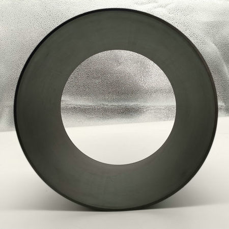
PEEK Plastic (polyetheretherketone)
PEEK material, also called polyether ether ketone, has grown enormously in popularity in recent years due to its versatility in applications. PEEK plastics meet higher requirements than standard or technical plastics and can therefore be considered high performance plastics.
This compact, sturdy type of plastic can be machined with high accuracy, resulting in beautiful, smooth surfaces. PEEK is ideally suited as a material for various applications with high quality requirements. The popularity of PEEK stems from its excellent mechanical properties and high resistance to corrosive substances products. Furthermore, its high melting point makes it suitable for subtractive processes such as CNC machining.
Here, we'll share PEEK machining guidelines to help you get the best from your PEEK machining process. Let's go right to it!
Machining Tidbits
• PEEK shapes are stronger and stiffer than most plastics but considerably softer than most metals meaning fixturing is critical.
• All PEEK grades are more abrasive on tooling than softer plastics like nylon and acetal. This especially true of the grades reinforced with glass and/or carbon fiber. Carbide tooling can be used for short runs. Part geometry, tolerances and grade will also influence tooling selection. Polycrystalline (PCD) tooling should always be considered long runs, tightly tolerance parts and for reinforced grades.
• PEEK has lower elongation than many other plastics. Deep hole drilling into heavy cross sections without enough coolant can lead to cracking.
• Coolant can be used while machining PEEK. Both water soluble and petroleum-based coolants may be used. Appropriate use of coolants will extend tool life and improve surface finish. Air, preferably from a cold air gun can also be used for small parts including those in which clean-up is difficult.
Turning
Positive geometries with ground peripheries are suggested for inserts. Fine grained C-2 carbide or PCD inserts are best. 360° chuck pressure is suggested to avoid distortion. Machined soft jaws or pie jaws should be used when turning thin walled, tubular shapes. Rough turning the chuck area of the stock is suggested to improve roundness. Internal plugs should be used to prevent thin walled parts from compressing and distorting.
Drilling
Care to minimize heat build-up must be taken especially when drilling holes that are more than 2X the diameter. Low helix drill bits and flood coolant are best for drilling holes. Peck drilling is suggested for swarf removal. Coolant fed drills are ideal for removing swarf and preventing excessive heat build-up.
Larger diameter holes are best approached using a 2-step process incorporating a drilled pilot hole (1/2” diameter
maximum) and boring to finish diameter. Drilled holes ½” diameter and smaller can be machined using a standard carbide drill. Holes up to 2” diameter can be machined using an insert drill such as Iscar Chamdrill. Pocketing is suggested for mill set ups. To avoid breakout of the back side consider milling from both sides or leaving .005-010” that you remove by milling with a small end mill.
Threading
Single point inserts with flood coolant should be used for threading during turning. Two fluted, non-coated spiral carbide taps are suggested for tapped holes. Tapping should be done with a cutting fluid. Tight tolerance tapped holes may require one size larger tap than would generally be needed to tap aluminum or steel. When thread milling floating tap heads can minimize tap breakage common with smaller sizes taps.
Milling
Part fixturing is critical for milling as high spindle speeds and fast travel are preferred to minimize frictional heat buildup and material pullout. Cutters should be designed with positive geometry. Climb milling is recommended over conventional milling as it provides better chip removal, lower tool wear and better surface finish. End mills with 4 flutes should be used when possible. Generally during milling step overs should be limited to 25% tool diameter and depths of cut 50% of tool diameter to achieve an optimal surface finish.
Sawing
Band sawing is the preferred method of cutting PEEK shapes. It can be used for both straight and contoured cuts of plate in addition to rod and tubular bar. Saw blades should be chosen based on material thickness and precision and must have enough clearance to minimize heat build-up. Triple chip blades 2.5-3.5 teeth per inch are suggested. We have good results with .035” thick x 1” wide blades. Generally, fewer teeth per inch than metals require will help reduce heat build-up. We suggest 3 teeth per inch at a band saw speed of 2500 ft per minute as a starting point. Coolant (fluid and or air) should be used.
Table sawing can be used but care must be exercised to ensure safety. Residual stress within shapes can cause material to close in on the blade. When using a table saw partial cuts into the thickness are best. Rip and combination blades with carbide tips are suggested. We suggest fewer teeth per inch than would be used on metals or wood. A 60 teeth 12” diameter rip and combination blade should yield smooth cuts on plates up to 1/2” thickness.
Chop saws and radial arm saws may be used but care must be exercised to ensure safety. Residual stress within shapes can cause material to close in on the blade. When using a chop saw repeated partial cuts are required to minimize heat buildup when cutting cross sections greater than 2”. Rip and combination blades with carbide tips are suggested. We suggest fewer teeth per inch than would be used on metals or wood. A 60 teeth 12” diameter rip and combination blade should yield smooth cuts.