#White Papers
Testing of extruded sheet materials
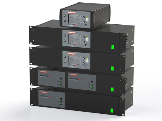
The DCCT Pro2 range
Introduction
Manufacture of film and sheet polymer materials is typically carried out by means of a sheet mould, which may be several metres wide. Such moulds are commonly fed by one or more screw extruders, and the sheet is fed through calendaring rolls and is supported whilst cooling. It may then be rolled, or slit into panels, dependent on thickness.
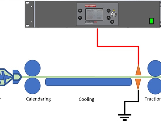
Refer to Fig 1, Typical Extrusion Process
Whilst extruder lines are reliable, it may be desirable or necessary to carry out electronic pinhole detection on the extruded material, and this is clearly most efficiently carried out at the earliest possible stage in the process. This will normally be before rolling or slitting as shown in the example below; The electrodes are placed either side of the material to be tested and the instrument applies a continuous charge to the upper electrode. Any flaw in the material will allow a spark to pass between the electrodes and this will be detected & reported by the instrument.
Refer to Fig 2, Location of Test Electrodes
Buckleys DCCT instruments are ideal for this purpose, as they provide a highly stable high voltage DC output, with an adjustable sensitivity alarm. Additionally, these instruments are fitted with software-controlled zero-volt relay connections which operate in synchronisation with the alarm, allowing interconnection with PLC controllers, or a variety of other devices, for example, a paint spray for marking. Additionally, the instrument is fitted with interlock connections thus the HV output can be remotely controlled, and disabled, should the safety case require it. There is also a fault counter.
The instrument is capable of creating 0.9-40kV, and the alarm threshold ranges from 10 to 400uA. Both of these may be defined by the user, and the settings can be locked by means of a Manager-defined passcode.
The minimum voltage required to carry out a test on any particular material is dependent on the thickness of the material. The maximum voltage that can be used is dependent on the thickness, and the dielectric strength, of the material. Typically, test voltages are specified somewhere between these limits, in order to ensure detection of non-perpendicular faults in the material, whilst minimising, or ideally eliminating, any risk of the test itself causing the damage it is intended to detect.
Corona Discharge & Material Current Draw
Whilst we associate air as being an extremely effective electrical insulator, we are also familiar with sparks travelling through the air – lightning is an obvious example, but the spark plugs of petrol engines, and piezo gas lighters are perhaps more relevant. In these cases, the design of the system ensures that the electrode voltage rises very rapidly, and decays almost instantly when the spark occurs – this is not helpful for a continuous inspection system as we need the voltage to exist at all times, and the spark to only occur when a flaw passes between the test electrodes. Accordingly, the HV system has to produce, and maintain, a significant voltage difference between the test electrodes.
There are two physical phenomena which counteract the maintenance of this voltage difference;
The first of these is Corona Discharge. This is a process by which the air surrounding a charged body, such as the electrode, becomes ionised, and in so doing, moves away from the charged body – this causes a continuous flow of current from the electrode, and is largely dependent on the voltage applied – although it is also significantly affected by the shape of the body – pointed items will cause a more significant discharge than spherical ones – and electrodes with metallic brushes are particularly susceptible to this effect.
The second is Material Draw. Highly insulating materials are able to act as capacitors, and will hold a dielectric charge on their surface, particularly if there is a counter-charge on the opposite surface. As the material passes through the electrodes, there will be deposition of charge on the material surface, which is drawn away from the electrode by the material passing, and this represents a further flow of current from the electrode. The magnitude of this current is dependent on the material being tested, the width of the electrode, and the velocity of the material past the electrode.
It can be seen, therefore, that as the thickness of the material being tested is increased, the required voltage increases, and this leads to an increase in the Corona Discharge current. As the width of the material is increased, or the speed of the material is increased, the Material Draw current is also increased. These factors must be considered when specifying an HV system. The sum of the Corona Current and Material Draw Current is the Total Quiescent Demand Current, Iq for convenience.
Buckleys have material testing capability and are pleased to offer advice on the expected Corona and Material Draw currents for planned installations, however, due to the nature of discharges and their very specific dependence on the surroundings and environment, this advice can only ever be general in nature.
Instrument Output Limits
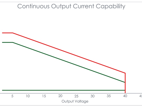
Buckleys DCCT instruments are designed to provide a limited output current, primarily to ensure that the output remains within the limits specified by the IEEE to prevent a lethal shock to anyone accidentally touching the HV electrodes or wiring. This has the effect of limiting the output power at any given voltage, as can be seen in the graph in Fig 3.
Refer to Fig 3, Typical Output Performance at 40kV
The red line on the graph in figure 3 shows the performance limit as a limit for continuous current across the range of output voltage of the DCCT instrument. Ideally, the current demand Iq at the required voltage will fall in the zone outlined in green. If however the demand current Iq is sufficiently high, it will cause the output voltage to drop. Provided that the resultant voltage remains sufficiently high to carry out the test reliably, this is acceptable, however, if it leads to a voltage below the necessary minimum, the test may not detect flaws.
This inevitably leads to a situation where some combinations of material thickness, extrusion width and extrusion speed will exceed the output of a single instrument.
Buckleys Solution
Accordingly, Buckleys has developed a modular design of DCCT which allows up to four electrodes to be controlled from a single command station. The modular units are packaged in a 2U 19” rack-mountable case, and are supplied with the necessary hardware for installation.
In the traditional approach, it was necessary to limit the width of the extrusion to that which could be scanned by a single HV source, or to purchase multiple instruments in order to connect to multiple electrodes.
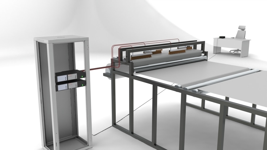
With the modular Buckleys DCCT Pro2, multiple electrodes can each be connected to a dedicated source, with a simple common control interface, allowing the testing of wider, thicker materials at higher line speeds. Additionally, each output stage contains its own relay driver, thus allowing more precise localisation of any flaws detected.
In the diagram below, two dual-channel units have been used to drive four independent electrodes. One of the units contains a control panel, although there is an option to mount this remotely if desired.
Summary and Conclusion
The thickness and width of the extruded material, and the extruder speed are the three key determining criteria in specifying a high-voltage pinhole detection system. An increase in any of these variables leads to an increased demand on the system.
The instrumentation limits are defined on grounds of safety and compatibility. Single instruments are generally not suitable for thick, wide and fast extrusion. Multiple instruments are able to resolve the issue but are costly and consume production space.
Use of a modular system allows a significant increase in system capability in a cost-effective, integrated and easily implemented way.