#Product Trends
Ultrasonic Transducer Beam Angle Explained: Frequency, Aperture, Near Field, and Side Lobes
Ultrasonic Transducer Beam Angle Explained: Frequency, Aperture, Near Field, and Side Lobes
A beam angle needs a definition before it needs a number
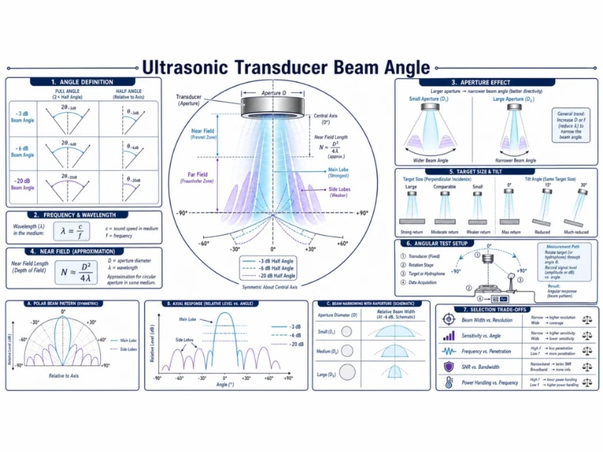
“Beam angle” is often treated as one fixed property, but a transducer does not project a cone with a hard edge. Acoustic pressure varies continuously with direction and distance. A catalogue angle may be measured between -3 dB points, -6 dB points, another threshold, or first nulls; it may describe transmit pressure, receive sensitivity, or a combined pulse-echo response. Those definitions produce different numbers for the same device.
Before comparing two ultrasonic transducers, ask for the level criterion, full angle or half angle, measurement plane, distance, medium, frequency, mounting, target or receiver, drive and signal processing. Without those conditions, “15 degrees” and “20 degrees” may not represent a real performance difference.
The beam is a spatial response
An active aperture contains many vibrating points. Their waves combine constructively and destructively in space. On axis, contributions may reinforce. Off axis, phase differences reduce the sum and can create nulls and side lobes. The resulting field depends on wavelength relative to the effective aperture and on the amplitude and phase distribution across that aperture.
A simple uniformly vibrating circular piston is useful for understanding trends, but a commercial transducer also includes a piezoelectric element, matching layers, backing, housing, protective face, adhesive, curvature, damping, and mounting boundary. These can change the effective aperture and introduce non-axisymmetric behavior. Use the piston model as an estimate, then measure the completed assembly.