#Product Trends
The linear guide rail systems on 3D printer axes
4 different types of guide system.
3D printing technology is advancing by leaps and bounds. One moment we are discussing making small toys to entertain children, and the next second we see news that a 3D printer has built a concrete building that can withstand an 8-magnitude earthquake. Given time, "3D printing a 3D printer" also seems possible.
But leaving prospects aside, what hobbyists and makers care more about are still desktop 3D printers — what types there are, how fast they print, and how much they cost. If you like getting to the bottom of things, or ever tried DIYing a 3D printer before, you must also have pondered this question: how do they move?
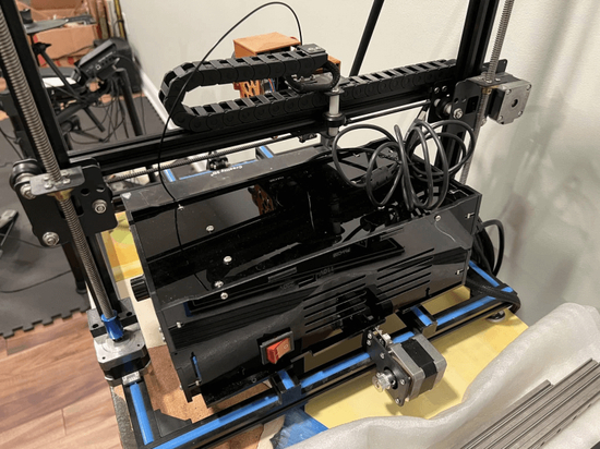
XYZ, I3 and CoreXY are currently the most popular styles of desktop 3D printers. This is how they move: the machine has one or several axes in the X, Y and Z directions of the 3D coordinate system. One end of each axis is equipped with a motor to provide power. Synchronous belts or leadscrews then convert the motor's rotation into linear motion along the X, Y and Z directions. Finally, with the linear guide rail systems in the 3 directions, the machine can position the nozzle at any point in the 3D space formed by the axes, extrude the filament, and create a 3D object.
Why are guide systems important?
The guide systems mainly serves 3 purposes during printing:
1. Precision: Realize tight tolerance, prevent wobble, and ensure the print head or heated bed installed on the guides moves linearly along the predetermined direction;
2. Smoothness: Reduce friction with bearings or rollers, and contribute to smoother motion;
3. Reliability: Guiding structures with excellent rigidity can improve machine reliability and contribute to more consistent prints over time.
The variety of guide systems
In general, the guide systems used on 3D printers include:
1. Wheels & profiles
2. Linear rods & bearings
3. Linear rails
4. Embedded linear rails
Wheels & profiles
Among all the guides, the combination of wheels and profiles is probably the most common and cost-effective. There are typically 3 to 4 rollers running along the V- or T-shaped groove of the profile to guide the movements.
The outer ring of the wheels is most commonly made of POM (Polyformaldehyde), and the inner ring is made up of steel and ball bearings. POM has high strength, low deformation, and excellent abrasion resistance, making it especially suitable for making printer wheels. With proper use, POM rollers can last hundreds of hours. Some manufacturers also use PC (Polycarbonate) to make wheels, which have even higher strength and longer life, though at a slightly higher price.
To ensure linear motion, the wheels should grip the profiles properly. Too loose and vibration can occur at high speeds. Too tight will increase wear — accumulated debris can pile up between the wheels and rails, causing bumpy or jittery motion. So users need to adjust the wheel tightness based on how the printer works, clean debris, and replace wheels when necessary. Compared to other guides, the wheel and profile combo requires more frequent maintenance.
Additionally, plastics have lower rigidity than metals. Wheel deformation during motion is hard to avoid, so printers using wheels generally have lower precision compared to those with steel guides.
The profiles commonly used on 3D printers are available in two types: V-slot profiles and T-slot profiles. As the names suggest, the main difference between them is the cross-sectional shape. Different profiles pair with different wheels to achieve good guiding effects.
Since the profiles are customizable, inexpensive, and with sufficient performance, the combination of wheels and profiles is the top choice for many DIY 3D printer builds.
Advantages
Good guiding performance, cheap and useful;
Abundant options, widely available;
Easy to install, use, and modify;
Disadvantages
Lower precision;
More prone to vibration;
Requires more frequent maintenance.
Linear rods & bearings
The limitations of wheel and profile guides have led DIYers and manufacturers to shift more attention to another combination with superior precision and stability — linear rods and bearings. In the past few years, rod and bearing guides have become almost synonymous with guide systems for 3D printers. At least 2 rods and 2 bearings are needed for each axis of the printer. The bearings either wrap or cling to the rods, while connecting to carriages mounted with an extruder or heated bed, to guide the linear motion.
A linear rod, aka smooth rod, is simply a cylindrical steel rod, available in various sizes — 3D printers typically use 8mm diameter ones. Rods can be machined to high dimensional accuracy with very smooth surfaces. Paired with ball bearings, properly assembled rods can achieve fairly good linear motions.
And yes there are also drawbacks of being smooth. When used for guidance, the rods need to be fixed at both ends with metal clamps. Also, bearings can not only move linearly but also rotate 360° around the cylinders. That's why they need to be attached to bearings on another parallel rod to let the extruder or heated bed move linearly. Parallelism between two rods can be challenging, especially for DIYers.
So, using shaft guides means higher precision and stability on one hand, but also larger footprint and weight, along with higher assembly difficulty on the other.
The bearings used with rods are mainly U-groove bearings and linear bearings made entirely of steel. U-groove bearings resemble wheels that can roll along the rods. Linear bearings have a cylindrical sleeve on the outside, with several rows of balls on the inside that can cycle along the shaft. Both can accomplish smooth guidance with minimal friction.
Rods and bearings are long lasting, only requiring occasional cleaning of buildup on the rods and lubricating the bearings. If the rods are enclosed in a housing instead of acting as the frame, disassembling the housing and lubricating the bearings is straightforward. However, replacing worn out bearings after prolonged use can be slightly tricky.
Advantages
Excellent guiding performance, high precision, moderate cost;
Abundant options, widely available;
Low maintenance frequency;
Disadvantages
Larger footprint and weight when enclosed;
Parallelism can be a problem;
Replacing bearings can be tricky.
Linear rails
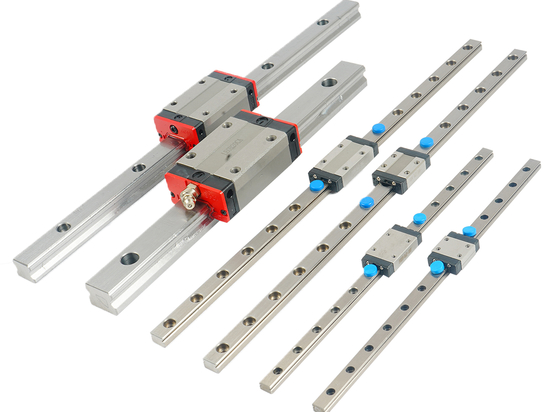
Linear rail, also referred to as linear guide, has been trending in recent years. The steel rail part has a track on each side, and the sliders nested on it contain 2 sets of ball bearings that can cycle along the tracks. In addition to industrial 3D printers, more and more desktop manufacturers are also using linear rails in their high-end product lines.
Although both are made of steel, when it comes to actual work, linear rails are less susceptible to bending and vibration compared to rods. This is mainly attributed to their unique mounting method. Rods are only fixed at both ends, while linear rails have mounting holes at regular intervals on the surface, allowing them to be tightly secured to the housing or other support structures.
This ensures stable linear motion and improves print quality on one hand, and increases the speed limit by preventing excessive shaking at high speeds on the other. This is one of the reasons J1 can achieve high-speed printing.
During assembly, linear rails can guide a single axis without pairing, saving space and weight to make the machine more lightweight and compact. There is also no need to worry about rail parallelism.
It all sounds great, but what's the catch? The price. Rough calculations show that while the sliders for linear rails have similar prices to the bearings for rods, the rails themselves cost about 2.5 – 4 times that of a pair of rods at equivalent lengths. In comparison, rods are cheap and good enough. Weighing the extra cost against performance gains, most DIYers would still opt for rods and bearings.
For maintenance, linear rails are similar to the former, requiring regular lubrication of the bearings. Exposed rails also need occasional cleaning.
Advantages
Very high precision;
Supports high-speed printing;
Small footprint, convenient to use;
Disadvantages
Cannot serve as support structures, needs to be installed on profiles, etc.;
Expensive.
Embedded linear rails
Instead of using the above guides directly, some manufacturers, for the purpose of advancing technical capabilities or catering to specific products, are also exploring better solutions.
The core strengths of linear rails lie in the high rigidity of the steel rails and the precise, smooth motion enabled by the ball bearings. These advantages are preserved in embedded linear rails.
When making the Linear Modules, FUYU embeds two steel strips into the inner walls of the aluminum alloy housing, then CNC grinds the steel precisely into rails with micron-level machining accuracy. Also, with the wider embedded rails, rigidity is further improved without increasing weight, better suiting high-power CNC operations — after all, ordinary 3D printers do not require such extreme rigidity.
Compared to directly mounting linear rails on the surface of extrusions, embedding the steel rails inside the linear modules prevents dust buildup on the rails, reducing maintenance frequency. It also makes the modules more lightweight and compact, so that an expensive machine does not end up looking like a DIY enthusiast's project. However, embedding linear rails does pose considerable manufacturing challenges for the producer, with no cost advantage over normal linear rails.
Advantages
Same as linear rails: very high precision, supports high-speed printing, small footprint;
Rail rigidity further improved;
Lower maintenance frequency with rails enclosed;
Disadvantages
Expensive;
Not suitable for DIY.


