#Industry News
Based on the equipment specification sheets and commissioning notes from the site.
This field report breaks down the measured parameters, selection logic, and installation pitfalls behind the system
Guangzhou, China — In a 1,200 m² precision machining workshop in South China, a compressed air system built around an Airhorse AHB-20A rotary screw compressor, a 500 L vertical air receiver, and a refrigerated dryer has completed 1,000+ hours of continuous operation without unplanned downtime, according to commissioning records reviewed by our engineering desk. The project replaced a mixed-brand legacy setup that had been causing chronic moisture carryover, pressure fluctuations, and an average of one unplanned shutdown every eight weeks.
This field report breaks down the measured parameters, selection logic, and installation pitfalls behind the system, based on the equipment specification sheets and commissioning notes from the site.
1. System Specification & Nameplate Data
Screw Air Compressor
The Screw Air Compressor, model/specification Airhorse AHB-20A, has the following key parameters and verified values: Motor Power is 15 kW / 20 HP; Free Air Delivery (FAD) is 2.1 m³/min @ 10 bar (belt-drive variant); Working Pressure is 10 bar (145 psi); Noise Level is 64 dB(A); Motor Protection is IP54 (motor), air-end IP55; Dimensions (L×W×H) are 940 × 800 × 1,075 mm (tank-mounted combo); and Weight is ~335 kg (combo configuration).
Air Receiver
The Air Receiver is a Vertical pressure vessel with a Volume of 500 L. Its Design Standard is GB150 / ASME equivalent, Q345R carbon steel.
Refrigerated Dryer
The Refrigerated Dryer, model/specification Airhorse AH-10SG class, has a Pressure Dew Point of +3 °C (at rated conditions); a Max Inlet Air Temp. of ≤ 60 °C; and an Ambient Temp. Limit of ≤ 35 °C (for rated performance).
Piping
The Piping uses a Seamless steel / flexible connection with a Connection Size of 3/4 inch (compressor outlet).
2. Technical Specifications: Operating Envelope & Derating Boundaries
The AHB-20A is a belt-driven, oil-injected screw compressor using a GHH (Germany) air-end and SKF rotor pair, with the electric motor assembled to Jiangtian production standards and Siemens/Schneider electrical components. The cooling system is rated for an ambient temperature range of −5 °C to +45 °C; beyond the upper threshold, the air-end discharge temperature and motor current draw rise disproportionately, and the refrigerant dryer’s condensing capacity begins to fall.
For system selection, two derating factors are decisive and frequently underestimated on site:
(1) Altitude derating. Compressor FAD is rated at standard atmospheric conditions. At elevations above sea level, the mass of air drawn in per cycle drops. A commonly cited rule of thumb is a ~3% reduction in volumetric output per 300 m (≈1,000 ft) of elevation gain, though the exact correction should be taken from the manufacturer’s altitude curve.
(2) Inlet temperature derating for the dryer. The refrigerated dryer’s rated capacity is published at a specific inlet air temperature (typically 35–38 °C) and ambient temperature (≤ 35 °C). If the compressor room regularly exceeds 35 °C ambient—common in unshaded workshops in southern China—the dryer’s effective dew point rises, and moisture breakthrough occurs even when the dryer is “running normally”. Sizing the dryer at 1.2× the compressor’s rated FAD is a practical hedge for ambient temperatures up to 40 °C.
3. Selection Guide: Matching the Package to the Duty
The AHB-20A sits at the 15 kW / 20 HP class. Selection decisions should not be made on motor kW alone; the required pressure, duty cycle, and air quality class determine whether this model is appropriate or whether the system must step up.
3.1 Selection Comparison for Common Workshop Duties
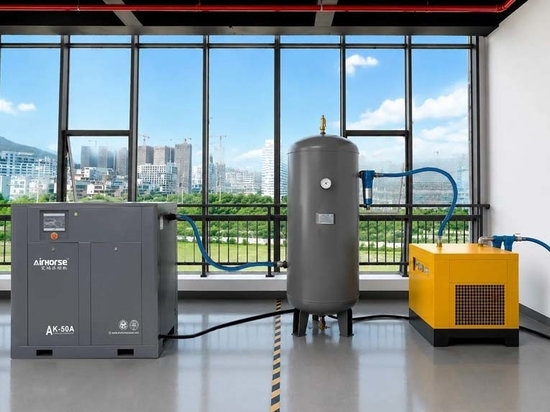
For a General workshop / assembly (6–8 bar, intermittent) scenario, the recommended compressor logic is an AHB-20A at 10 bar setting; fixed-speed load/unload is adequate if air demand is stable. The dryer type should be Refrigerated (+3 °C PDP), and the receiver sizing rule is ≥ 1/3 of compressor FAD (in liter). Note that the setup in the photograph fits this profile; the receiver absorbs demand spikes and reduces motor starts.
For CNC machining / laser cutting (clean, dry, continuous), the recommended compressor logic is an AHB-20A or 16 bar PM VSD screw air compressor; pressure stability is critical. The dryer type should be Refrigerated + coalescing filter (oil carryover < 0.01 ppm), and the receiver sizing rule is ≥ 1/2 of FAD. Note that oil and moisture cause tool wear and optics contamination; filtration after the dryer is mandatory.
For High ambient (> 40 °C) or high altitude (> 1,000 m) scenarios, the recommended compressor logic is to not select on nameplate FAD alone — apply altitude/temperature correction and oversize by 15–25%. The dryer type should be an Oversized refrigerated dryer or desiccant dryer if PDP < +3 °C required, and the receiver sizing rule is to increase receiver volume by the same correction factor. Note that the dryer is the first component to become undersized in hot environments.
For a Critical process requiring PDP −20 °C to −40 °C, the recommended compressor logic is that the AHB-20A is suitable as the compressor, but the refrigerated dryer is not sufficient. The dryer type should be a Desiccant / adsorption dryer, and the receiver sizing rule is that a receiver is still required for buffer; desiccant dryers have purge air loss. Note that refrigerated dryers cannot achieve sub-zero PDP; selecting one for a −40 °C duty is a specification error, not an installation error.
4. Application Notes: Installation Pitfalls Observed in the Field
The commissioning of this skid revealed several repeatable errors that are easy to overlook on paper but expensive in operation. These are documented here as field notes, not generic checklist items.
Pitfall 1 — The receiver drain is treated as an accessory, not a control point
The air receiver is the primary liquid-water knockout in the system. If the manual or automatic drain is not opened/cycled, condensate accumulates and is carried downstream into the dryer, overloading the dryer and raising the pressure dew point even when the dryer’s refrigerant circuit is functioning correctly. On this site, the original installation had a manual ball valve on the receiver drain that was inaccessible behind the tank leg. The commissioning fix was to install a zero-loss automatic drain with a strainer upstream, and to route the discharge to a visible floor drain so that a failure is immediately noticeable.
Pitfall 2 — The interconnecting pipe slopes the wrong way
The pipe from the compressor discharge to the receiver inlet must slope downward toward the receiver, not upward or level. A level or back-sloping run allows condensate to pool in the pipe during cooling, creating a water trap that slugs into the dryer on the next load cycle. In the photographed installation, the flexible connection between the compressor and the receiver is short and visibly pitched toward the tank—a detail worth inspecting on any similar setup.
Pitfall 3 — The dryer is installed without a bypass, and the filters are in the wrong order
The correct sequence is compressor → receiver → pre-filter → dryer → post-filter → end use. Two failure modes were observed in the legacy system on this site: (a) the dryer had no bypass, so any dryer maintenance shut down the entire plant air supply; and (b) a particulate filter had been installed upstream of the receiver, which clogged rapidly and caused a pressure drop that the operator compensated for by raising the compressor setpoint—masking the restriction and wasting energy. The corrected installation includes a full-flow bypass around the dryer and places the pre-filter between the receiver and the dryer, with the post-filter after the dryer.
Pitfall 4 — The compressor is boxed into a hot corner
The AHB-20A’s cooling system is rated to +45 °C ambient, but that rating assumes adequate airflow across the cooler. A compressor placed in a recess with less than 50 cm clearance from walls and no forced ventilation will cycle its cooling fan against its own hot discharge air. In summer conditions, this manifests as high discharge temperature trips (typically above 100–105 °C) even when the compressor is not mechanically overloaded. The site correction was to relocate the unit to a position with cross-flow ventilation and to add a thermostatically controlled wall fan—a low-cost intervention that eliminated the trips without changing the compressor’s setpoints.
5. Engineer’s Field Note: What the Data Sheet Does Not Tell You About “Starting Up”
Contributed by the commissioning engineer on the project, with 11 years of rotary screw system field experience.
I have commissioned more than 60 Airhorse AHB-series units across Guangdong and Guangxi. The AHB-20A is a mechanically straightforward machine—the GHH air-end and belt drive are serviceable, and the IP54 motor is appropriate for a workshop with moderate dust. But three things consistently catch new owners off guard.
First, the first 50 hours are not a “run-in” period you can ignore. On this unit, the initial belt tension was set at the factory, but after the first 50 hours of thermal cycling, the belt had stretched enough to slip under peak load—not enough to fail, but enough to reduce delivered pressure by roughly 0.3–0.4 bar at the outlet. The controller showed no alarm; the only symptom was that downstream actuators were slower than expected. Retension the belt at 50 hours, then at 500 hours, then annually. If you skip the 50-hour check, you will not notice the loss until a production line starts rejecting parts.
Second, the refrigerated dryer’s +3 °C dew point is a rated value, not a guaranteed value in a hot room. The AH-10SG class dryer is rated at ≤ 35 °C ambient and ≤ 60 °C inlet air temperature. In a workshop where the compressor room reaches 42 °C in August, the dryer’s condensing capacity falls and the actual pressure dew point can drift to +8 °C to +10 °C. The air is still “dry” by the gauge, but it is wet enough to corrode uncoated aluminum tooling overnight. If you are in a hot climate, specify the next larger dryer frame or provide forced ventilation in the compressor room. The incremental cost of the larger dryer is recovered by not scrapping rusted parts.
Third, the automatic drain on the receiver is the highest-failure-rate component in the entire package—and it fails silently. A stuck-closed drain fills the receiver with water; a stuck-open drain bleeds compressed air 24/7 and runs up the electricity bill. On this project, we fitted a level-sensing electronic drain with a high-level alarm contact wired back to the compressor controller. That is not standard on a base AHB-20A package, but after replacing three mechanical timer drains in two years on a previous site, I now treat it as a mandatory upgrade. If the budget does not allow a level-sensing drain, at minimum test the drain manually every Monday morning and log the discharge. A drain that produces no water for two consecutive checks is a drain that has failed closed.
The AHB-20A itself has been reliable: the air-end bearing life is rated at 35,000–40,000 hours before replacement, and the unit is designed for continuous duty in 2–3 shift operations (5,600–8,500 hours/year). The failures I see are almost never in the compressor’s rotating group. They are in the interface between the compressor and the rest of the system—the drain, the belt, the dryer sizing, and the ventilation. Get those four right, and the machine will outlast the production line it serves.