
#Industry News
Geographic Engineering and Implementation Principles of Centralized Laboratory Gas Supply Systems
Geographic Engineering and Implementation Principles of Centralized Laboratory Gas Supply Systems
Geographic Engineering and Implementation Principles of Centralized Laboratory Gas Supply Systems
Introduction to Centralized Gas Distribution
Modern analytical laboratories, university research centers, and advanced manufacturing facilities require a continuous, unfluctuating stream of high-purity process gases to support delicate instrumentation and automated processing equipment. Historically, facilities relied on decentralized gas storage layouts, where individual high-pressure cylinders were situated directly at laboratory workbenches or adjacent to sensitive testing apparatus. However, modern safety mandates, structural efficiency standards, and strict micro-contamination guidelines have driven a comprehensive shift toward centralized gas infrastructure layouts.
Implementing a comprehensive centralized laboratory gas supply system offers a robust, industrially verified solution. By consolidating bulk source cylinders, high-capacity liquid dewars, and automated supply manifolds into a single, isolated external structure, engineering teams optimize space utilization while vastly improving safety standards. Successfully executing this infrastructure requires addressing distinct spatial logistics, geographic facility design factors, and mechanical piping installation standards.
Centralized Laboratory Gas Supply Systems
Centralized Laboratory Gas Supply Systems
Geographic Layout Design and Facility Zoning
The spatial planning phase of a centralized laboratory gas supply system dictates its long-term reliability and regulatory compliance. Project engineers must first establish clear geographic layout parameters based on the chemical footprint of the gases in use. Standard safety protocols require dividing the gas network into distinct spatial zones across the facility grounds.
The source zone, which includes gas storage pads or dedicated cylinder rooms, should ideally be located on the ground floor or along an external perimeter wall of the building structure. This strategic positioning simplifies cylinder logistics, allowing delivery trucks to load and unload heavy cylinders without navigating tight internal corridors. For highly volatile, toxic, or flammable gases like hydrogen or methane, the source room must feature dedicated explosion-relief walls, spark-proof electrical infrastructure, and robust perimeter ventilation systems that interface directly with emergency exhaust scrubbers.
Between the external source zone and the internal point of use, engineering teams plot the distribution path. This layout path should follow the shortest, most direct route through dedicated utility chases or overhead service corridors. Minimizing unnecessary turns, elevation changes, and complex joints reduces gas flow resistance, controls line pressure drops, and limits potential down-line leak vectors across the facility footprint.
Material Selection and Pipeline Metallurgy
Preserving gas purity as it travels from the centralized storage pad to analytical instruments requires strict adherence to pipeline metallurgy standards. Standard commercial plumbing materials like copper or low-grade stainless steel are entirely unsuitable for high-purity laboratory networks due to risks of internal outgassing, particle shedding, and chemical degradation.
Ultra-high purity gas loops require seamless, electropolished ASTM A269 316L stainless steel tubing. The internal surces of electropolished tubing undergo specialized chemical treatments to achieve an ultra-smooth finish. This smooth surface prevents trace gas molecules, ambient moisture, and micro-particles from becoming trapped inside microscopic metal pits, guaranteeing that gases reach instruments with zero loss in purity. For standard laboratory utilities, bright annealed stainless steel pipelines provide a cost-effective, high-reliability alternative that balances budgetary constraints with strict contaminant control.
Mechanical Component Integration and Loop Architecture
A high-performance centralized laboratory gas supply system relies on a network of interconnected mechanical modules designed to maintain stable system pressures and deliver uninterrupted gas flow:
Source Manifolds
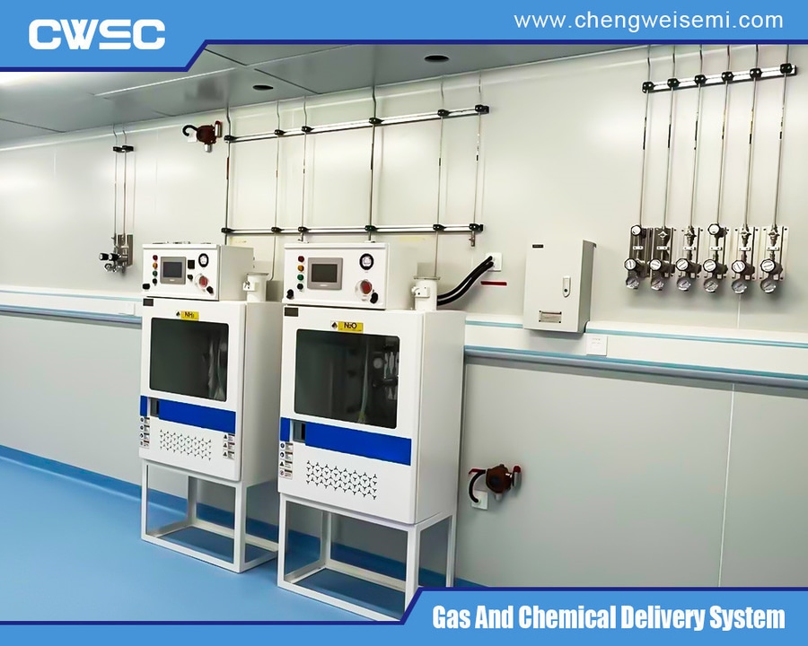
The primary distribution loop starts at the automatic changeover manifold panel. These assemblies link multiple gas cylinders into two parallel banks, designated as the primary source and the reserve source. Integrated differential pressure sensors continuously track cylinder depletion rates. When the primary bank drops below a set operational pressure threshold, the manifold automatically switches to the reserve bank without causing downstream pressure fluctuations or interrupting laboratory testing.
Intermediate Distribution Nodes
Once the main gas line enters a laboratory floor, it routes through a valve manifold box or localized distribution panel. These nodes split a single high-capacity line into multiple secondary branches, allowing facility managers to isolate individual laboratory rooms or benches for maintenance without shutting down the entire building network.
Point of Use Regulators
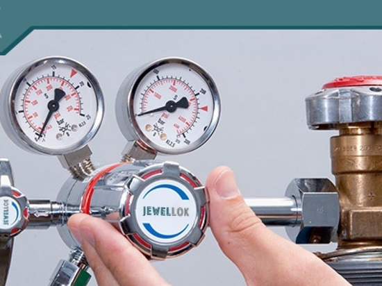
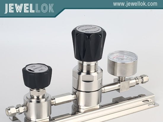
The final delivery stage occurs at local point of use panels installed at laboratory benches or inside fume hoods. These panels feature dual-stage stainless steel diaphragm regulators and micro-metering valves, giving researchers precise control over delivery pressures and flow rates tailored to specific analytical applications like GC-MS or ICP-MS testing.
Field Quality Control and Validation Testing
The physical assembly and validation of a centralized laboratory gas supply system require strict compliance with cleanroom-grade construction standards. Mechanical installation crews must follow rigid quality control steps to protect the integrity of the internal pipeline surfaces.
All permanent connections on stainless steel gas lines are executed using automated orbital tungsten inert gas welding equipment. During the welding process, technicians maintain a continuous back-purge of high-purity argon gas inside the tubing. This purge prevents internal oxidation, commonly known as sugaring, which would otherwise ruin gas purity and create rough areas that trap trace contaminants.
Following physical installation, the entire pipeline network must pass a multi-tiered safety and pressure verification process. First, contractors perform a high-pressure drop test, pressurizing the system with clean, dry nitrogen to 1.5 times the maximum intended working pressure and holding it for at least 24 hours to confirm zero mechanical seal degradation. Second, high-purity specialty lines undergo helium mass spectrometer leak detection testing, targeting a strict leak boundary rate below 1×10⁻⁹ mbar liters per second to ensure total system integrity.
Centralized Laboratory Gas Supply Systems
Centralized Laboratory Gas Supply Systems
Summary of Infrastructure Engineering Benefits
Successfully deploying an engineered centralized laboratory gas supply system delivers clear operational, financial, and safety advantages for modern research and manufacturing centers. Consolidating high-pressure gas sources into isolated, geographically optimized rooms removes industrial hazards from workbenches, creating a safer environment for laboratory personnel. Furthermore, automated changeover networks eliminate process downtime, minimize raw gas waste, and provide clean, stable operating conditions that preserve instrument calibration accuracy. Investing in high-grade stainless steel metallurgy, precise pressure control modules, and rigorous validation protocols ensures long-term facility compliance and supports advanced scientific exploration.
For more about centralized laboratory gas supply system, you can pay a visit to Chengwei Semiconductor at https://www.chengweisemi.com/product/centralized-gas-pipeline-system-and-central-gas-supply-system-for-speciality-gases/ for more info.