#Industry News
What the Brake Pedal Safety Uproar Reveals About Conductive Slip Rings in Automotive Safety Testing
How Extreme Braking Tests Highlight the Unsung Hero of Automotive Data Acquisition
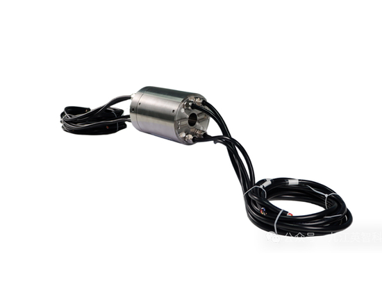
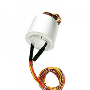
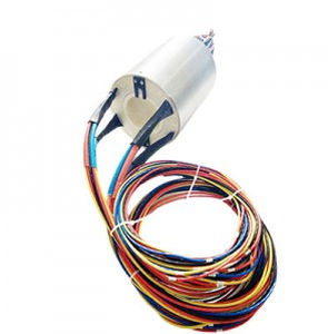
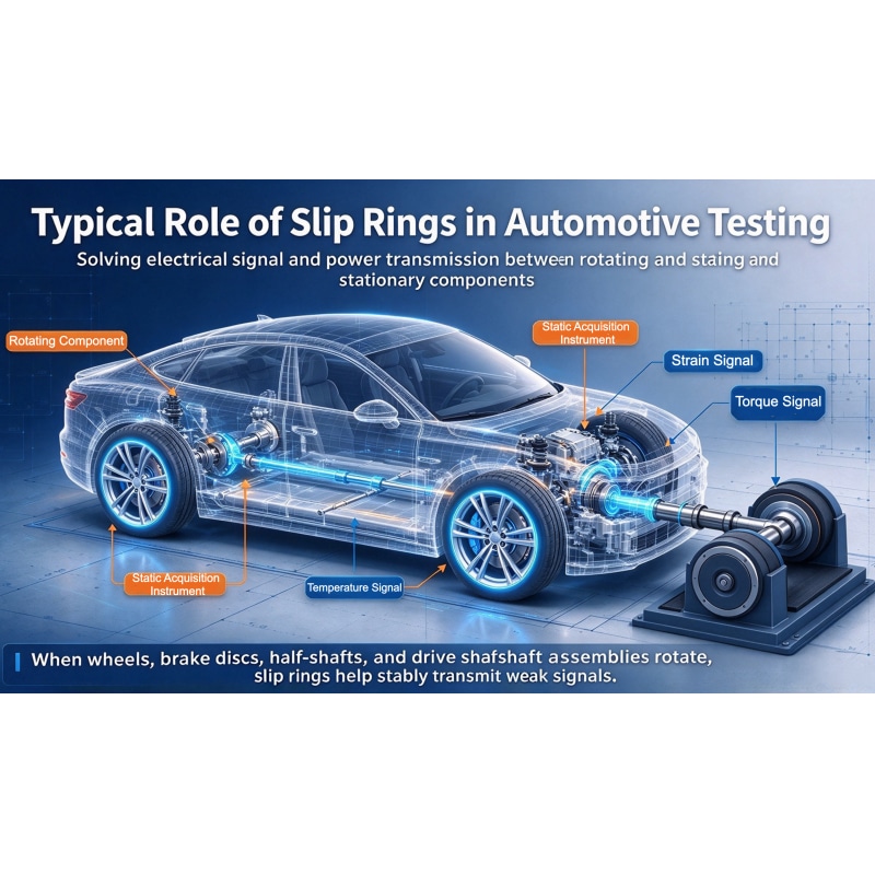
Recently, discussions in the automotive industry about pedal bracket fractures during extreme braking tests have again drawn attention to the completeness of vehicle development validation. Regardless of the specific model or test plan, automotive braking, chassis, and powertrain development all depend on transmitting electrical signals and power to rotating components. Conductive slip rings are one of the common components used to solve this type of rotating electrical connection. The following introduces, purely from an industry testing perspective, the typical positions and roles of conductive slip rings in automotive testing.
1. Wheel-End Six-Component Force Sensor | Brake and Chassis Load Testing
Installation:Between the wheel hub and rim; either an integrated conductive slip ring or a wireless telemetry solution can be selected.
It acquires multi-axis forces and moments such as longitudinal braking force, vertical load, lateral force, and braking torque, obtaining the true load on each wheel and supporting suspension and knuckle load analysis as well as load-spectrum input. At the same time, it transmits signals from brake-disc thermocouples, strain gauges, and acceleration sensors to monitor brake temperature rise, vibration, and impact, used for thermal-fade evaluation, strength simulation, and fatigue validation.
Note: Pedal bracket load must be tested separately and cannot be inversely derived from wheel-end six-component force. Not every brake test requires a six-component force sensor and slip ring.
2. Brake Disc / Brake Assembly Bench Slip Ring | Brake Component Durability Validation
Installation:Spindle end of the brake disc / brake drum test bench
When the brake rig conducts durability, thermal fatigue, and brake NVH tests, the slip ring transmits thermocouple and strain-gauge signals from the rotating side to the stationary data-acquisition equipment, monitoring the brake disc temperature field and rotating-part stress, evaluating thermal deformation and thermal-crack risk, and verifying brake structure stability under continuous braking.
Sensors on the stationary side, such as friction-pad sensors, are usually wired directly and do not require a slip ring.
3. Half-Shaft / Drive-Shaft Torque Test Slip Ring | Drivetrain and Brake Coupling Testing
Installation: Half-shaft or drive-shaft shaft end (hollow-shaft or shaft-end slip ring; some models are dust- and water-resistant)
In real-road tests and chassis bench scenarios, it acquires dynamic half-shaft torque and torsional strain during hard braking and ABS operation. It quantifies the transmission of reverse braking torque along the drivetrain chain, providing a basis for strength analysis of the drivetrain and chassis connection points.
Half-shaft torque cannot directly represent pedal bracket load; the two must be validated separately.
4. Powertrain / Dynamometer Bench Slip Ring | E-Drive and Powertrain System Testing
Installation:Crankshaft, motor output shaft, dynamometer main shaft
In powertrain loading tests, it acquires torque, bearing temperature, and vibration data from rotating components. For NEV models, it is mainly used in combined regenerative-braking + hydraulic-braking conditions to evaluate the influence of composite braking loads on the drivetrain.
E-drive composite loads are not directly transmitted to the brake pedal mechanism; their mechanical paths are independent.
5. Full-Vehicle Axle-Coupled Road Simulation Bench | Long-Term Chassis Durability Assessment
Installation: Spindle loading end, wheel-spindle sensor position
The lab reproduces road impacts and continuous braking loads to carry out chassis durability tests. If a rotating wheel-force sensor is used at the wheel end, the slip ring transmits force and torque signals. The bench closed-loop control relies on actuators’ built-in sensors; the slip ring is not the core of the control loop.
Supplementary: Easily Confused Similar Components
· Steering wheel clock spring: Provides rotational communication for the steering wheel and transmits airbag and button signals. Its mainstream structure uses a flat flexible cable and it is not a test-purpose conductive slip ring.
· In-wheel / hub motor: Development prototypes occasionally use slip rings to transmit rotor sensor signals; production solutions mostly use wireless telemetry or resolvers, so slip rings are not the mainstream choice.
Summary
The core value of conductive slip rings is to stably transmit sensor power and weak signals under rotating conditions, widely used in automotive testing such as wheel-end six-component force, brake rigs, half-shaft torque, and dynamometer benches. Whether to use a slip ring, and which specification to select, is determined by the test objective and test plan.