#Product Trends
OGI vs Acoustic Imaging Cameras for Gas Leak Detection
At Raythink | Raytron Industrial, we use industrial imaging to make hard-to-see conditions easier to act on. This guide compares optical gas imaging (OGI) and acoustic imaging cameras for Gas leak detection.
At Raythink | Raytron Industrial, we use industrial imaging to make hard-to-see conditions easier to act on. This guide compares optical gas imaging (OGI) and acoustic imaging cameras for Gas leak detection.
The choice begins with the signal produced by the leak. OGI visualizes infrared contrast created by a compatible gas plume. Acoustic imaging maps sound or ultrasound from a pressurized release. Both can help teams find where to look, and they solve different inspection problems.
What each camera sees
Comparison point OGI camera Acoustic imaging camera
Primary signal Infrared radiation absorbed by a compatible gas Airborne sound or ultrasound from a leak or other source
Best starting point A target gas that matches the camera configuration A pressurized leak that produces a usable acoustic signal
Typical image A moving gas plume or infrared contrast over the scene An apparent sound source over a visible scene
Main field variables Gas configuration, background, distance, focus, wind, and viewing angle Pressure, distance, frequency range, plant noise, reflections, and obstructions
First result Location of an imageable gas release Location of an apparent sound source
Follow-up when needed Gas confirmation, concentration, rate, exposure, or compliance measurement Gas identity, rate, equipment confirmation, exposure, or compliance measurement
Here, acoustic imaging refers to sound cameras that visualize airborne sound or ultrasound from leaks, not contact ultrasonic testing or acoustic emission testing.
When OGI is the better fit
OGI is a good fit when the camera configuration matches the target gas. The camera renders the gas plume as infrared contrast against the scene, helping teams inspect valves, flanges, fittings, vessels, and pipework from a stand-off position.
A single OGI model does not suit every gas application. The exact gas list, spectral band, detector, lens, and configuration determine fit. Raythink’s guide to how optical gas imaging works explains the imaging principle, while which gases OGI camera configurations can detect provides gas-compatibility context.
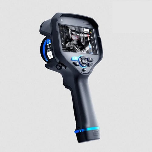
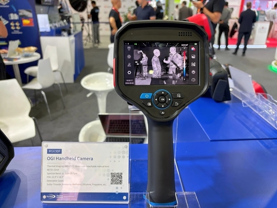
Raythink | Raytron's RG630F OGI Handheld Camera on display at OGA 2026
A representative OGI application is SF₆ leak localization in high-voltage switchgear. SF₆ was listed among the target gases for Raythink RG630F OGI Handheld Camera configuration. Teams can scan accessible breakers, gas-insulated switchgear (GIS) enclosures, and fittings from a stand-off position, making an otherwise invisible release easier to localize.
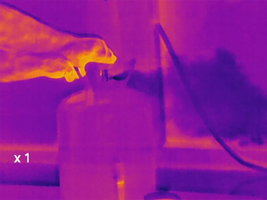
SF6 leak visualization using thermal imaging
OGI performance also depends on field conditions. Wind, viewing distance, background temperature and contrast, focus, and atmospheric interference all shape plume visibility. EPA Appendix K provides a useful technical reference for these variables in specified U.S. OGI surveys.
When acoustic imaging is the better fit
Acoustic imaging is a good fit for pressurized equipment that produces a detectable sound or ultrasound. A microphone array compares signals arriving from different directions and overlays the apparent source location on a visual image.
Compressed-air distribution is a practical example. A sound map can help a team narrow down the likely leak location around a fitting, hose, or valve from a stand-off position, even when a visual gas plume is not the most useful signal. Acoustic imaging can also help screen other pressurized utility and process equipment, provided the leak produces a detectable acoustic signal.
Acoustic performance depends on the sound level and surrounding conditions. Low pressure differential, competing plant noise, reflections, distance, obstructions, and unsuitable frequency settings can all make a source harder to locate. Select a camera with a frequency range and operating specifications suited to the equipment and inspection conditions.
Some acoustic cameras estimate leak size or flow from sound data. These estimates are useful for prioritizing repairs, but pressure, backpressure, leak type, distance, and operating state affect the result.
Match the method to the inspection task
Inspection task Useful starting method What it helps answer
Visualize a compatible gas plume OGI Is there an imageable release at a valve, flange, fitting, or process enclosure?
Scan a compressed-air route Acoustic imaging Which fitting, hose, or valve is the likely sound source?
Identify the gas or assess exposure Direct gas monitoring or sampling What is present, and what does it mean for the decision?
Quantify a release rate A quantitative method suited to the source How large is the release under the measured conditions?
Inspect a hazardous area Equipment with the appropriate marking and configuration Is the equipment suitable for the area classification and application?
Detector resolution, microphone count, and advertised range are useful specifications, but they do not replace the fit between the signal, the site, and the inspection objective.
Field conditions shape the result
For OGI, plume visibility changes with gas response, viewing angle, background, temperature contrast, wind, weather, and focus. A different viewpoint or background can make a meaningful difference.
detecting gas leak by optical gas imaging camera
For acoustic imaging, pressure differential, source geometry, distance, noise, reflections, and overlapping sources shape the sound map. Moving closer, isolating a source, or selecting a different frequency range can improve localization.
What happens after localization
OGI and acoustic imaging help teams narrow the search. The next instrument depends on the decision that follows.
For gas concentration, oxygen deficiency, flammability, or toxic exposure, use direct-reading monitoring and testing suited to the hazard. OSHA’s direct-reading monitor guidance describes the role of these instruments for toxic and combustible gases and oxygen conditions.
For a leak rate, use a quantitative method that defines the source, operating conditions, and required uncertainty. EPA Appendix K is a protocol for finding the presence and location of applicable leaks; rate measurement requires a method designed for that purpose.
How to choose a gas leak-detection camera
Start with five questions:
What gas are you targeting, and is the camera configured to detect it?
Is the release likely to produce a useful acoustic signal?
What distance, access, and viewing path are available?
What background, wind, weather, noise, and source-overlap conditions are expected?
What result is needed: localization, gas confirmation, exposure measurement, leak rate, or reporting?
Conclusion
OGI is the natural starting point when the inspection centers on a gas plume that matches the camera configuration. Acoustic imaging is the natural starting point when the leak produces a distinct sound in pressurized equipment. In many facilities, the two methods complement each other: one localizes the signal, and the other method confirms the gas, exposure condition, or release rate.
For a plant-specific comparison, share the target medium, equipment type, inspection distance, site conditions, area classification, and desired result. Discuss an OGI camera configuration with Raythink | Raytron Industrial for an application-fit discussion.