

#Product Trends
How to Calculate Solenoid Pull Force for Automation Machines
Learn how to calculate solenoid pull force for automation machines. Understand force formulas, key factors, and how to select the right solenoid.
How to Calculate Solenoid Pull Force for Automation Machines
Chapter 1: Introduction of Calculate Solenoid Pull Force
Selection of the right actuator is essential for reliable operation of industrial machines within automation systems. Solenoids represent some of the most popular electromagnetic actuators because of their quick reaction, small size, reliable operation and easy structure.
However, one of the most critical parameters to evaluate is the pull force of solenoids.
Wrong choice of pull force can lead to a number of problems:
The mechanism will not be able to perform necessary operations.
The solenoid will be overworked, overheat, and break down.
The machine will become unstable while operating at a high speed.
Increased mechanical stresses will reduce the life of the solenoid.
Therefore, it is very important for engineers to learn how to calculate pull force for solenoids to choose the right actuator and increase the performance of machinery.
This article provides information about calculation of pull forces of solenoids, influencing factors and practical approaches to choose solenoids for automation systems.
Chapter 2:What is the pull force of solenoid?
Pull force represents electromagnetic force that is generated by the solenoid coil when a plunger is pulled inside after the application of electrical power.
Pull force is the ability of the solenoid to move or hold a mechanical load.
In automation equipment, the pull force is usually evaluated in such units as:
N
Gram force (gf)
Kilogram-force (kgf)
Lbf Pound-force
Conversions: -
1 N ≈ 101.97 gf 1 kgf ≈ 9.81 N
Thus, for example, a solenoid with pull force 50 N is able to produce:
50 × 101.97 = 5098 gf or around 5.1 kgf of pulling force.
Chapter 3: Basic Solenoid Pull Force Formula
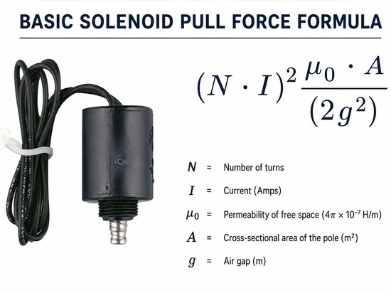
The theoretical electromagnetic force of solenoids can be calculated using the following formula:
F = B 2 A 2 μ 0
Where:
F = Magnetic attractive force (N)
B = Magnetic flux density (T)
A = Effective pole area (m²) μ₀ = Permeability of free space
However, in practical applications, the calculation of magnetic flux density is complicated by the dependence on the following factors:
Number of turns of coil
Present
Magnetic materials
Length of air gap
Design of the plunger
Structure of core
So, manufacturers of solenoids provide the force-stroke curve that demonstrates actual performance of pull force.
Chapter 4:Pull Force and Air Gap
Air gap represents one of the main factors that influence solenoid pull force.
Rule of thumb:
Greater pull force = Lesser air gap
When the plunger is far:
High magnetic resistance.
The magnetic efficiency decreases.
The pull force decreases.
When the plunger is close:
Stronger magnetic circuit.
Greater magnetic pull.
The pull force is maximal.
Example:
A tubular solenoid includes:
Stroke Pull Force Distance
10 mm stroke 20 N
Stroke 5 mm 45 N
Stroke 1 mm 100 N
Therefore, it is very important for engineers to check the necessary pull force at the actual stroke and not only at maximal force value.
Chapter 5:Main Factors That Influence Solenoid Pull force
5.1 Current & Voltage of Coil
The electromagnetic force is proportional to the power of the coil.
Increase in the voltage will lead to increase in the following parameters:
Current of the coil
Strength of field (magnetic)
Pull force
For DC solenoids:
Power = Voltage x Current
Example:
A solenoid 12V and 24V with identical design may have different force performance.
However, increased voltage also means more:
Heat production
Use of energy
Temperature of the coil
Therefore, there should be a compromise between force and thermal performance.
5.2 Coil Design
The coil is the main part of the solenoid.
The most important coil parameters include:
Number of turns
GAGE OF WIRE
Thicker wire can conduct more current.
Defiance
However, lower resistance leads to more current, and more power consumption.
The professional manufacturer of solenoids optimizes:
Coil winding design
Size of copper wire
Insulation material
Duty cycle
5.3 Material of Plunger
The material of the plunger has a direct influence on the magnetic efficiency.
Common materials for plungers are:
Low carbon steel
Iron, pure
Magnetic stainless steel
Materials with high magnetic permeability can offer:
Increase in pull force
Decrease in response time
Increased efficiency
Also, they can be improved through surface treatment such as plating with nickel.
5.4 Stroke Length
Distance of movement of the solenoid plunger is referred to as stroke.
Some typical strokes of automation solenoids:
1 mm.
3 mm
5 mm.
10mm
20mm
Generally, increased stroke length means decreased pull force.
For example:
The solenoid produces:
2 mm stroke, 80 N
40 N @ 8 mm stroke
20 N at 15mm stroke
Therefore, it is necessary for engineers to define:
Required stroke length
Force at required stroke
Working frequency
before choosing the solenoid.
Chapter 6:How to Calculate Necessary Pull Force for Automation Machines
Practical approach to calculation:
Step 1: Computation of Mechanical Load
It is necessary to establish the size of the load that has to be moved.
Example:
A machine has to pull a locking mechanism:
Load mass:
10kg
Gravitational force:
10 * 9.81 = 98.1 N
Step 2: Friction and Safety Factor
Automation systems always require a margin of safety.
Recommended safety factor:
Light applications: 1.5 x
Industrial applications: 2×
Heavy duty applications: 3x
Calculation:
Force required:
98.1 N × 2 = 196.2 N
Therefore, a solenoid with at least:
Pulling Force 200 N has to be chosen. _
Step 3: Check Force at Actual Stroke Length
Never choose according to maximum force.
Example:
Requirements:
Stroke : 10 mm
Force = 200 N
Rating of the solenoid:
300 N at 0mm stroke is just:
150 N at 10 mm stroke
Always check the force curve of the solenoid provided by the manufacturer.
Chapter 7:Choosing Solenoid Pull Force for Automated Applications
Different automation systems require different force.
Small Automated Devices
Applications:
Sensors
Small locks
Medical devices
Electronics
Normal force:
5-30 N
Medium Automation Equipment.
Applications:
Conveyors
Assembly machines
Test equipment.
Normal force: .
30-150 N _
Industrial Automation Heavy
Applications:
Robotics
Industrial fittings
Packaging machines
Normal force:
150-1000 N+
Chapter 8:How to Improve Solenoid Pull Force
Solenoid Pull Force is an important parameter in various technical fields including industrial automation, robotics, valves, locks and motion control. Poor force generation by a solenoid may lead to inability to execute required tasks and even downtime of equipment.
In order to make solenoid pull force improvement you have to consider the following parameters: magnetic circuit, coil design, mechanical part design and work conditions. Here is some list of efficient solutions that will help you enhance the performance of your solenoid.
1. Increase Coil Power and Current
The magnetic field generated by the coil determines the solenoid magnetic force. The increase of coil current may increase the magnetic force.
You can implement the following methods:
Increase the operating voltage in the range of rated values;
Decrease the resistance of the coil;
Improve wire diameter and number of coil turns;
But in the case of increasing the power, the problem of temperature increase appears. You have to balance these two factors in your solenoid design to avoid coil overheating.
2. Shorten the Air Gap Length
The air gap between plunger and magnetic core influences greatly the performance of solenoid.
The short air gap provides:
Greater magnetic efficiency;
Greater pulling force;
Faster response time;
In your solenoid design you have to optimize the plunger and magnetic core location in order to avoid unnecessary gaps.
Often the maximum pull force is observed when the plunger is close to the core. Therefore, it is necessary to verify the force in the actual work position.
3. Increase the Quality of Magnetic Materials
The performance of the solenoid depends on the material properties of plunger and housing.
Materials with higher magnetic permeability increase magnetic flux and increase the pull force.
Usually these materials include:
Pure Iron;
Low-carbon steel;
Magnetic stainless steel;
Such approach will allow you to increase the force without changing the size of the solenoid.
4. Optimize Magnetic Circuit Design
The proper design of magnetic circuit increases its efficiency and minimizes the magnetic leakage.
Improvements include:
Optimize core shape;
Increase the magnetic effective area;
Improve plunger alignment;
Reduce Magnetic Resistance;
Custom solenoid design provides optimal magnetic structure for your specific application and therefore higher performance.
5. Decrease Mechanical Friction
The mechanical friction lowers the output force of the solenoid.
To increase performance you have to:
Provide smooth movement of plunger;
Provide correct surface treatment;
Provide good machining tolerances;
Reduce excess mechanical load;
The low friction mechanism allows converting more of electromagnetic force into mechanical one.
6. Utilize Proper Voltage Control Technology
In many automation systems you need high starting force but lower holding power. To solve this problem, you can apply to the following techniques:
Voltage boosting circuits;
PWM control;
Energy saving control modules;
Such methods provide a high initial force but consume less energy during operation.
Chapter 9:Tips on How to Avoid Common Mistakes in Choosing a Solenoid
The right choice of the appropriate solenoid guarantees a correct functioning, extended life time and stable operation of the industrial machinery. There are many common selection mistakes which could lead to the lack of sufficient force, heating up, breakage or increased expenses for the maintenance of the equipment. Knowing about those mistakes, you will have an opportunity to choose the right solenoid.
1. Negligence in Estimating the Necessary Force and Stroke
The most frequent mistake is a choice of the solenoid depending on its size or appearance. Such parameters as the force and stroke length are of the highest importance. If the solenoid has no ability to produce sufficient force to achieve the needed stroke, then the position of the load will not be correct.
When selecting a solenoid, please remember:
Needed force of pushing or pulling
Length of stroke of the operation
Mechanical resistance and weight of the load
Safety factor
Always estimate the solenoid force chart, but not just the maximum force.
2. Selection of the Wrong Voltage
Another mistake is associated with the selection of the wrong voltage specification. All solenoids are produced at the definite operating voltages, for example, DC 5V, 12V, 24V or 48V.
Using the solenoid at the higher voltage, you may encounter with such problems as:
Heating up
Destruction of coils
Shorter life span
Using the lower voltage, you may obtain:
Insufficient magnetic field
Too slow reaction
No action
Make sure that you check the voltage of the solenoid and compare it to your equipment power supply.
3. Neglecting the Duty Cycle and Heat Dissipation Conditions
Sometimes, engineers take into consideration only the force, ignoring the working period. A solenoid designed for the intermittent operation will be heated during the continuous work.
Consider:
Necessary duty cycle
Operating frequency
Temperature of the environment
Conditions for heat dissipation
4. Not Taking Account of the Installation Space
The solenoid can operate effectively and be considered as the failure, because there is no possibility to install it into the equipment. Check:
Mounting dimensions
Orientation of connectors and shaft
Space for mounting
5. Selecting a low-quality solenoid
The cheapest solenoid can be not reliable enough. Inappropriate materials, poor magnetic design and lack of testing will cause increased failure rate.
How to choose the right solenoid supplier:
Information about the force tests
Tests of the life time
Quality inspection information
Avoiding of these common mistakes will give engineers an opportunity to select the right solenoid solution.
Chapter 10:. Conclusion
When designing automation machines, it is a very important step to calculate pull force of solenoids. In addition to the necessary load, engineers have to take account of stroke distance, duty cycle, voltage, coil design and safety factor.
The right choice process is the following:
Calculate mechanical load.
Provide a safety margin.
Check the force at working stroke.
Check voltage and duty cycle.
Choose the right solenoid actuator.
Right choice of solenoid allows increasing reliability of the machine, extending its life and improving automation performance.
Cooperation with a professional manufacturer of solenoids can help to optimize magnetic design and get the optimal balance between force, size, power consumption and cost for industrial automation applications.
Chapter 11: FAQs on solenoid pull force calculation
Q1: What is solenoid pull force?
Solenoid pull force is the force generated by the solenoid to move or hold a mechanical load.
Q2: How to calculate the force of a solenoid?
The force of a solenoid can be calculated from its magnetic flux, area of poles, current, coil design and distance of air gap.
Q3: Does stroke affect the pull force of a solenoid?
Yes. With increased stroke distance, pull force decreases.
Q4: What safety factor is used for a solenoid?
Usually, industrial automation systems have safety factor 1.5 to 3 times greater than calculated load.
Q5: What influences DC solenoid pull force?