#Product Trends
Ultrasonic Transducer Circuit Matching: Capacitance, Resonance, Drive Voltage, and Ringing
Ultrasonic Transducer Circuit Matching: Capacitance, Resonance, Drive Voltage, and Ringing
An ultrasonic transducer is part of an electrical and acoustic system
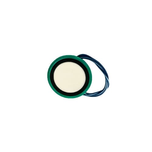
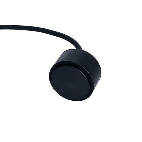
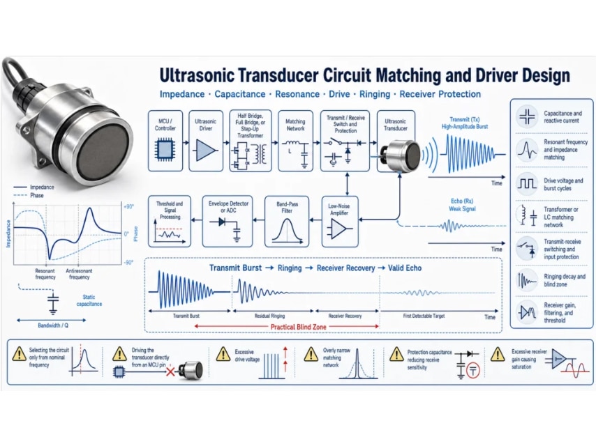
A transducer with the correct nominal frequency is not automatically compatible with an existing circuit. Transmit strength, current demand, recovery time, receive sensitivity, blind zone, noise immunity, and long-term reliability depend on the interaction between the piezoelectric element, housing, cable, driver, matching network, transmit-receive switch, protection, analog front end, and signal-processing settings.
This article focuses on circuit-level integration. For the broader information needed in a custom inquiry, see our custom ultrasonic transducer specification guide.
Start with measured electrical data, not only a frequency label
Request or measure the impedance curve around the intended operating band. Important values include resonant and antiresonant frequencies, impedance magnitude and phase, static capacitance, dielectric loss where relevant, sensitivity, allowable drive, and the test condition. Housing, potting, cable length, mounting, temperature, and production variation can shift these values.