
#Industry News
Engineering Principles of Ultra-High Purity Laboratory Gas Distribution Systems
Engineering Principles of Ultra-High Purity Laboratory Gas Distribution Systems
Engineering Principles of Ultra-High Purity Laboratory Gas Distribution Systems
Introduction
In modern analytical laboratories, research facilities, and advanced manufacturing environments, the integrity of a laboratory gas distribution system is foundational to operational success. These systems are responsible for transporting high-purity, toxic, corrosive, and flammable gases from centralized supply sources directly to point-of-use instruments and experimental workstations. As analytical techniques achieve lower limits of detection, moving from parts-per-million (ppm) to parts-per-billion (ppb) and parts-per-trillion (ppt) sensitivities, the tolerance for background contamination drops to near-zero. Consequently, the design, material selection, fabrication, and automation of a laboratory gas distribution system must adhere to strict engineering codes to ensure both process purity and personnel safety.
laboratory gas distribution system
laboratory gas distribution system
Material Science and Surface Engineering
The choice of metallurgy within a laboratory gas distribution system is the first line of defense against gas contamination and systemic degradation. Standard commercial piping materials are wholly inadequate for high-purity or ultra-high purity (UHP) gas distribution due to internal surface roughness, outgassing, and susceptibility to chemical corrosion.
2.1 Stainless Steel Grades and Processing
The industry standard for high-purity lines is 316L stainless steel, a low-carbon alloy containing molybdenum to enhance resistance to pitting and crevice corrosion. For demanding applications, double-melted alloys such as Vacuum Induction Melted (VIM) and Vacuum Arc Remelted (VAR) 316L stainless steel are utilized. The VIM/VAR process minimizes non-metallic inclusions, refines the alloy’s microstructure, and yields a highly homogeneous material. This structural consistency drastically reduces internal outgassing of trapped microscopic voids and provides a superior base for advanced surface finishing techniques.
2.2 Electropolishing and Surface Roughness
To eliminate mechanical micro-cracks, ridges, and particulate traps, internal surfaces undergo electrochemical polishing (electropolishing). This process selectively removes the macroscopic peaks of the metal surface via an electrolytic bath, reducing the internal surface roughness (Ra) to below 5 to 10 micro-inches (0.13 to 0.25 micrometers). Beyond smoothing the surface texture, electropolishing enriches the chromium-to-iron ratio at the surface layer. This chromium-rich passive oxide film acts as an inert barrier, preventing the underlying iron from interacting with corrosive trace gases or moisture, thereby preserving the purity of the process fluid.
Fluid Dynamics and Pressure Regulation Frameworks
Maintaining a stable, continuous flow profile while mitigating pressure fluctuations is critical for sensitive analytical hardware, such as Gas Chromatography-Mass Spectrometry (GC-MS) or Inductively Coupled Plasma Mass Spectrometry (ICP-MS). A robust laboratory gas distribution system relies on a engineered hierarchy of pressure containment and regulation.
3.1 Dual-Stage vs. Single-Stage Regulation
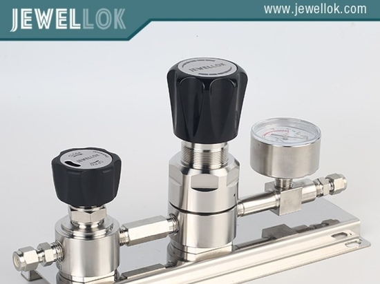
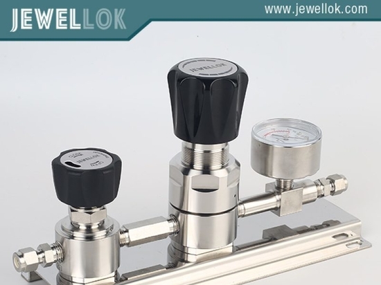
Centralized gas storage banks usually maintain gases at high pressures, often exceeding 2,000 to 3,000 psi. Delivering these gases safely to lab equipment requires step-down pressure reduction. Single-stage regulators reduce cylinder pressure to delivery pressure in one step. However, they suffer from the ‘supply pressure effect’ (SPE), where the delivery pressure rises as the source cylinder empties. To isolate point-of-use instruments from this variance, dual-stage pressure regulation frameworks are implemented. The first stage reduces the fluctuating source pressure to an intermediate level, while the second stage manages the intermediate pressure down to a steady, low-pressure outlet value, ensuring absolute analytical baseline stability.
3.2 Source Manifold Integration
Continuous gas delivery is achieved via automated changeover manifolds. These systems couple primary and secondary gas cylinder banks through internal software or differential pneumatic valving. When the active cylinder bank drops below a predetermined pressure threshold, the manifold automatically shifts flow to the reserve cylinder bank. This transitions the system smoothly without disrupting ongoing laboratory operations, preventing flow stagnation, back-diffusion, or pressure drops.
Fabrication Technologies and Structural Integrity
The assembly and joining of structural elements within a laboratory gas distribution system must be executed under stringent contamination-control protocols. Traditional threaded fittings or compression sleeves introduce structural dead-legs and represent potential leak paths under thermal expansion or physical stress.
4.1 Automatic Orbital Welding
For UHP systems, permanent joints are established exclusively through automatic orbital Gas Tungsten Arc Welding (GTAW). Orbital welding delivers highly repeatable, full-penetration welds that are free from interior oxidation, provided a constant backing gas of high-purity argon is maintained inside the tubing. The argon shield prevents oxygen from interacting with the molten weld pool, eliminating ‘sugar-coated’ or oxidized welds that would otherwise act as severe particulate generation zones and degrade the protective chrome-oxide layer.
4.2 Fitting Configurations
Where components must remain removable for service, such as regulators, filters, and valves, metal gasket face-seal fittings (such as VCR fittings) are mandatory. These configurations utilize a metal gasket compressed between two polished metal faces, providing a zero-clearance, metal-to-metal seal that prevents atmospheric infiltration and exhibits helium leak rates lower than 1×10^-9 atm cc/sec.
Safety Architecture and Automated Process Control
Distributing toxic, pyrophoric, or highly flammable gases within closed laboratory environments poses inherent risks. Consequently, modern laboratory gas distribution system designs integrate active safety monitoring alongside automated emergency response systems.
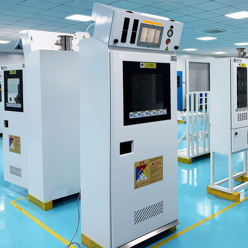
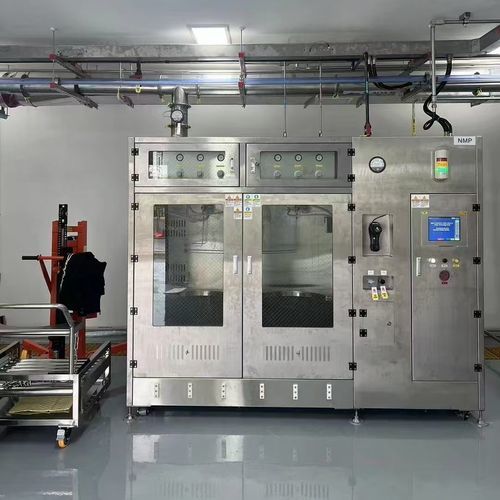
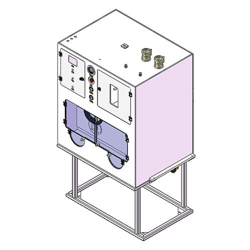
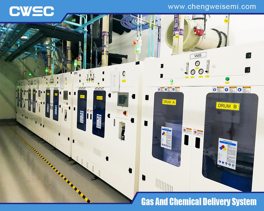
Gas Cabinets and VMBs: Hazardous gases are enclosed in continuously ventilated, negative-pressure gas cabinets or Valve Manifold Boxes (VMBs). Air velocities across the cabinet face are tightly regulated to ensure any microscopic leakage is exhausted safely away from technicians.
Automated Isolation Valves: Normally-closed (NC) pneumatic isolation valves are installed directly at the gas source. These valves require continuous pneumatic pilot pressure to remain open and will automatically isolate the gas cylinder upon loss of electrical power or control signal.
Gas Leak Detection Heads: Electrochemical, infrared, or catalytic gas sensors are located inside the enclosures and at point-of-use locations. If a target gas concentration crosses a safety threshold, the sensors trigger the safety plc to isolate source lines, actuate scrubbers, and flash local alarms.
Coaxial Piping Subsystems: High-hazard lines utilize coaxial (double-contained) piping. The internal process tube carries the target gas, while the outer coaxial containment tube is continuously monitored via a vacuum transmitter or a pressurized nitrogen purge loop to identify internal line breaches immediately.
laboratory gas distribution system
laboratory gas distribution system
Testing, Verification, and System Commissioning
Before a laboratory gas distribution system can be certified for process gases, a series of validation tests must be performed and recorded. The standard protocol includes structural pressure testing, helium mass spectrometer leak detection, and moisture/particulate verification.
Structural integrity is first verified using ultra-high purity nitrogen to perform a pneumatic pressure hold test at 1.25 to 1.5 times the maximum system working pressure. Following structural confirmation, helium leak testing is executed using out-outboard sniffing or inboard vacuum methods. The system must demonstrate an aggregate leak rate of less than 1×10^-9 atm cc/sec to prevent ultra-trace atmospheric contaminants from entering the fluid stream through micro-fissures. Finally, moisture and oxygen analytical instruments are connected at terminal outlets to verify that continuous purging has driven residual water and oxygen levels down to the required sub-ppb or single-digit ppm levels, ensuring the distribution network is fully optimized for immediate analytical use.
For more about laboratory gas distribution system, you can pay a visit to Chengwei Semiconductor at https://www.chengweisemi.com/laboratory/ for more info.