
#Industry News
The Piping Design and Installation Guidelines for Central Laboratory Gas Supply Systems
The Piping Design and Installation Guidelines for Central Laboratory Gas Supply Systems
1. Introduction
A central laboratory gas supply system is an essential component of modern laboratories, research institutions, universities, pharmaceutical facilities, chemical testing centers, and industrial research environments. It provides a reliable and controlled supply of gases from centralized storage areas to multiple laboratory workstations, analytical instruments, testing equipment, and experimental processes.
Compared with individual gas cylinders installed at each workstation, a centralized gas distribution system can improve laboratory space utilization, simplify gas cylinder management, reduce cylinder handling inside working areas, and support more consistent gas delivery. When properly designed and installed, it also helps laboratories establish effective gas safety procedures and maintain stable operating conditions for sensitive analytical instruments.
However, laboratory gases have different physical properties, purity requirements, pressure characteristics, and potential hazards. Nitrogen, oxygen, argon, helium, hydrogen, carbon dioxide, and specialty gases cannot always share the same pipeline design or safety configuration. Pipeline materials, pressure regulators, valves, fittings, ventilation, and monitoring equipment must therefore be selected according to the intended gas service.
This guide explains the major considerations involved in central laboratory gas supply system design, pipeline material selection, pressure control, installation, commissioning, and long-term maintenance.
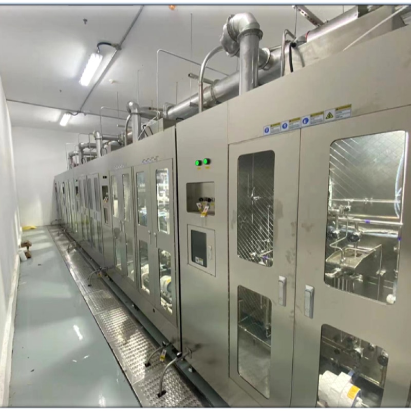
chemical delivery module (cdm) and chemical delivery system (cds)
2. Understanding the Structure of a Central Laboratory Gas Supply System
A central laboratory gas supply system typically consists of a gas storage area, a primary pressure regulation assembly, a distribution pipeline network, secondary pressure control equipment, terminal outlets, and associated safety devices.
The gas source may include high-pressure cylinders, cylinder bundles, liquid gas vessels, or other approved supply equipment, depending on gas consumption and facility requirements. Gas is transferred from the source through suitable pressure control equipment before entering the distribution network.
A typical system includes the following components:
Central gas storage area: Houses cylinders or other approved gas sources. The area should provide appropriate ventilation, access control, cylinder restraint, and segregation according to gas compatibility and applicable safety requirements.
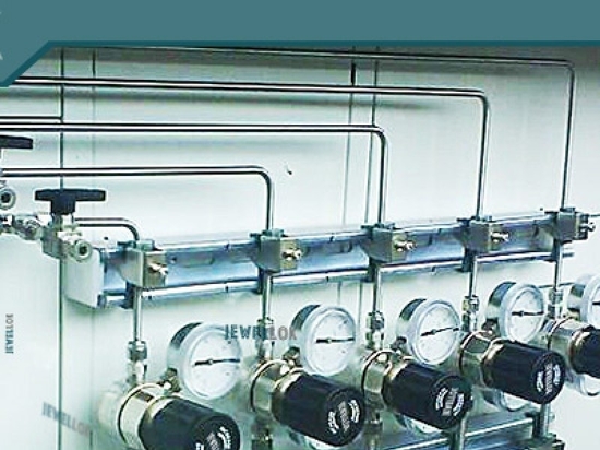
Primary gas supply panel: Controls the gas leaving the source. It may include pressure regulators, isolation valves, pressure gauges, filters, check valves, and source changeover equipment where required.
Gas distribution pipelines: Transport gases from the central supply area to laboratories and individual workstations. Pipeline routing should minimize unnecessary pressure losses, avoid incompatible services, and allow inspection and maintenance.
Secondary pressure regulators: Reduce or stabilize pressure near the point of use when the application requires a lower or more precise delivery pressure.
Terminal gas outlets: Provide controlled connections for laboratory instruments, analytical equipment, and experimental apparatus. Outlet configurations should prevent accidental connection to incompatible gas services.
Safety and monitoring equipment: May include pressure sensors, gas detectors, alarms, automatic shutoff valves, and emergency isolation devices, depending on the hazards and operational requirements.
The final system configuration should be based on a documented assessment of gas types, required purity, consumption, operating pressure, simultaneous demand, and laboratory safety requirements.
3. Pipeline Design: Gas Demand and System Capacity
Accurate gas demand calculations are the foundation of a reliable central laboratory gas supply system. An undersized pipeline can create excessive pressure drops and unstable instrument performance, while an unnecessarily oversized network can increase project costs and may complicate certain low-flow applications.
The design process should begin with a complete inventory of gas-consuming equipment.
For each instrument or workstation, engineers should identify:
Required gas type and purity grade.
Normal and maximum gas consumption.
Required inlet pressure and acceptable pressure variation.
Operating hours and expected usage patterns.
Number of outlets that may operate simultaneously.
Future expansion requirements.
The total connected load does not necessarily represent the actual peak demand. Engineers should establish a realistic diversity factor based on operating schedules and process conditions rather than assuming that every outlet will operate continuously at maximum flow.
Pipeline sizing must account for gas properties, operating pressure, temperature, pipe length, fittings, valves, regulators, and expected flow rates. Pressure loss calculations should consider both straight pipe sections and local resistance from bends, tees, filters, and other components.
For high-purity analytical gases, the pressure stability required by instruments can be as important as the overall flow capacity. Gas chromatography, mass spectrometry, spectroscopy, and other analytical applications may require carefully controlled delivery conditions.
The design should also consider the minimum operating pressure at the most remote outlet and the pressure variation that occurs when multiple instruments operate simultaneously.
A qualified engineer should perform the final sizing calculations using an appropriate compressible-gas flow method and the applicable engineering standards. Simple liquid-flow assumptions should not be applied indiscriminately to compressed gas pipelines.
4. Selecting Suitable Pipeline Materials
Pipeline material selection affects gas purity, corrosion resistance, mechanical integrity, leak tightness, and maintenance requirements.
Different gases and laboratory applications require different material specifications. The selection process should consider gas compatibility, operating pressure, temperature, moisture sensitivity, contamination limits, and the required level of cleanliness.
4.1 Stainless Steel Pipelines
Stainless steel is widely used in laboratory gas distribution systems because of its mechanical strength, corrosion resistance, and compatibility with many laboratory gases.
For high-purity applications, 316L stainless steel may be selected where its material properties and surface condition meet the required gas service specifications. Electropolished tubing or specially cleaned stainless steel tubing may be appropriate for applications that require reduced particle generation and surface contamination.
However, stainless steel grade alone does not guarantee high gas purity. Surface finish, cleaning procedures, welding quality, moisture control, fitting design, and installation practices also influence system performance.
Orbital welding may be used for suitable stainless steel tubing installations to improve weld consistency and reduce contamination risks when performed by qualified personnel under controlled conditions.
4.2 Copper Tubing
Copper tubing can be suitable for certain clean, noncorrosive gas services when the material, fittings, pressure rating, and cleanliness requirements are compatible with the application.
It should not be selected automatically for every laboratory gas. Gas compatibility, moisture content, oxygen-service requirements, and the possibility of chemical reactions must be evaluated before installation.
4.3 Specialized Materials
Certain corrosive or reactive gases may require specialized alloys, approved polymeric components, or dedicated gas delivery assemblies. The choice depends on the exact gas composition, concentration, moisture content, pressure, and temperature.
Materials that perform well with one gas may be unsuitable for another. Engineers should verify compatibility using reliable technical documentation and applicable industry standards.
All pipeline materials, valves, seals, regulators, and fittings should have pressure ratings appropriate for the maximum credible operating conditions.
5. Pressure Regulation and Control
Pressure control is one of the most important elements of central laboratory gas supply system design.
Gas cylinders and bulk gas sources may operate at pressures substantially higher than those required by laboratory instruments. A properly selected pressure regulation arrangement reduces source pressure to a suitable distribution pressure and maintains stable delivery as operating conditions change.
A typical arrangement includes primary pressure regulation near the gas source and secondary regulation near the laboratory or point of use, where necessary.
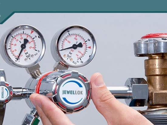
Primary regulators should be selected according to inlet pressure, outlet pressure, flow capacity, gas compatibility, and required control stability. For high-purity gases, regulators designed for clean gas service can help reduce contamination risks.
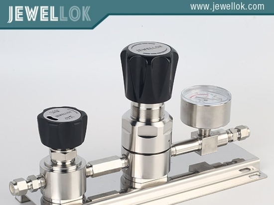
Diaphragm-based regulators may be appropriate for certain high-purity applications because they can support clean gas pathways and precise pressure control when correctly specified. However, regulator selection must also consider gas compatibility, seat materials, internal construction, and operating conditions.
For gases with unstable supply pressure or high consumption variation, engineers may need to evaluate automatic changeover systems. These systems can switch between primary and reserve gas sources to support continuity of supply.
Changeover systems should be configured to avoid unacceptable pressure interruptions and should provide suitable status indication or alarms when required.
Each gas service should have clearly defined operating pressure limits. Pressure relief devices, overpressure protection, and isolation arrangements must be selected and installed according to the system design and applicable codes.
6. Pipeline Routing and Laboratory Layout
Effective pipeline routing reduces pressure loss, simplifies maintenance, and supports laboratory safety.
The main distribution route should be planned before construction begins. Engineers should coordinate the gas pipeline layout with architectural plans, electrical installations, ventilation systems, fire protection equipment, water services, and laboratory furniture.
Pipelines should be supported at appropriate intervals and protected against vibration, impact, mechanical damage, and unauthorized interference.
Where practical, distribution routes should remain accessible for inspection and maintenance. Concealed installations should be designed so that critical joints and components can be inspected or serviced as required by the applicable standards.
Different gas services should be clearly identified using consistent labels and the relevant local color-coding conventions. Labels should indicate the gas identity and, where useful, flow direction and service information.
Gas lines must not be identified by color alone. Written labels and compatible outlet connections provide additional safeguards against incorrect connections.
Incompatible gases should be segregated where required by their chemical properties and the applicable regulations. Flammable, oxidizing, toxic, corrosive, and inert gases may require different storage, routing, ventilation, monitoring, and emergency isolation arrangements.
Hydrogen and other flammable gases require particular attention to ignition sources, ventilation, leak detection, and the suitability of electrical equipment. Toxic or corrosive gases may require gas cabinets, local exhaust ventilation, dedicated monitoring, and automatic shutoff systems based on a formal risk assessment.
Oxygen systems require materials and components suitable for oxygen service. Oil, grease, and other combustible contamination must be controlled because they can create serious fire hazards in oxygen-rich environments.
7. Installation Procedures and Quality Control
Professional installation is essential to ensure that a laboratory gas pipeline system performs as designed.
Before installation, the project team should verify the approved drawings, material specifications, equipment data sheets, gas compatibility requirements, and construction quality plan.
Step 1: Verify Materials and Components
Check tubing dimensions, material certificates where required, regulator specifications, valve pressure ratings, fitting types, seals, and terminal outlet configurations.
Materials should be stored in clean conditions and protected from moisture, dust, oil, and other contaminants. Components intended for high-purity gas service should remain sealed until installation whenever practical.
Step 2: Prepare the Installation Area
Confirm pipeline routes, support locations, equipment clearances, access requirements, and coordination with other building services.
The installation area should be prepared to minimize the introduction of construction debris and contamination into the gas distribution network.
Step 3: Install the Pipelines
Cutting, deburring, cleaning, joining, and welding should follow approved procedures appropriate to the material and gas service.
For high-purity stainless steel systems, controlled orbital welding or other qualified joining methods may be specified. Welding parameters, purge conditions, and inspection requirements should be established before work begins.
Open tube ends should be capped during installation interruptions. Tools and consumables used for clean gas systems should be suitable for the application and maintained in clean condition.
Step 4: Install Valves and Pressure Control Equipment
Install isolation valves, pressure regulators, filters, gauges, sensors, and other components according to the approved drawings and manufacturers’ instructions.
Equipment should be oriented for safe operation, inspection, and maintenance. Flow direction, regulator inlet and outlet requirements, and instrument connection specifications must be observed.
Step 5: Label and Document the System
Apply permanent gas identification labels and verify that each outlet corresponds to the intended gas service.
Update the as-built drawings to reflect actual pipeline routes, isolation points, regulator locations, and equipment identifiers.
8. Testing, Commissioning, and Gas Purging
A laboratory gas supply system must be inspected and tested before it is placed into service.
Testing should follow a documented commissioning plan based on the gas service, pipeline design, pressure rating, applicable standards, and equipment manufacturers’ requirements.
8.1 Pressure and Leak Testing
The completed pipeline should undergo the specified pressure and leak tests using an approved test medium and procedure.
Test pressure, duration, acceptance criteria, and isolation arrangements must be established by qualified personnel. Pneumatic testing can store substantial energy and therefore requires special precautions, exclusion zones, and controlled pressurization.
Oxygen, flammable gases, and toxic gases should not be used as casual substitutes for an approved test medium. The selected method must be appropriate for the pipeline and its intended service.
Leak detection methods may include approved leak-detection solutions, pressure decay procedures, or suitable instrument-based testing. The method should be compatible with the system’s cleanliness and material requirements.
8.2 Purging and Cleaning
After testing, the pipeline may require purging to remove air, moisture, residual test medium, particles, or other contaminants.
Purging procedures should be developed for the specific gas service and system configuration. The purge gas must be compatible with the pipeline, and discharge must be directed to a safe location or suitable treatment system.
Oxygen deficiency, flammability, toxicity, and environmental discharge hazards must be considered. Purging should not create an uncontrolled release into occupied laboratory spaces.
For high-purity systems, additional verification may be necessary to demonstrate that moisture, oxygen, or other contaminants are within the required limits.
8.3 Functional Commissioning
Commissioning should verify pressure regulation, flow capacity, valve operation, changeover performance, alarms, gas detection, and emergency shutoff functions where installed.
Each terminal should be checked against the approved gas identification and pressure requirements. Relevant test results should be recorded before the system is accepted for operation.
9. Safety Requirements and Risk Management
Laboratory gas safety depends on the interaction between engineering design, equipment selection, operating procedures, and personnel training.
A formal risk assessment should identify the hazards associated with each gas and determine the required protective measures.
Important safety provisions may include:
Secure cylinder storage and appropriate cylinder handling procedures.
Adequate ventilation in storage and equipment areas.
Gas detection for services that present significant leakage hazards.
Automatic isolation or emergency shutoff where required by the risk assessment.
Clearly accessible emergency isolation valves.
Suitable pressure relief and overpressure protection.
Segregation of incompatible gases and appropriate separation from ignition sources.
Written operating procedures and emergency response plans.
Personnel training in leak recognition, alarm response, and safe cylinder replacement.
The need for gas cabinets, automatic shutoff valves, exhaust ventilation, and continuous monitoring depends on the gas properties, quantity, supply pressure, room configuration, and applicable regulations.
Designers should consult relevant local building and fire codes, occupational safety requirements, gas-specific standards, and recognized engineering guidance. In the United States, applicable requirements may include provisions from NFPA, OSHA, and relevant mechanical, fire, and plumbing codes, depending on the installation.
No single standard applies identically to every laboratory. The governing requirements should be established at the beginning of the project.
10. Maintenance and Long-Term Performance
Regular maintenance helps preserve gas purity, pressure stability, system availability, and operational safety.
A maintenance program should cover central supply equipment, pressure regulators, automatic changeover panels, valves, filters, pipeline supports, terminal outlets, gas detectors, and alarm systems.
Inspection intervals should be based on manufacturer recommendations, service severity, regulatory requirements, and the laboratory’s risk assessment.
Maintenance activities may include checking regulator performance, inspecting for physical damage or corrosion, verifying pressure readings, testing alarms, confirming detector calibration, and examining cylinder restraints.
Filters should be replaced according to their condition and specified service life. Regulators and valves should be serviced or replaced when inspection results indicate deterioration or when their performance falls outside the specified limits.
Any modification to the pipeline network should be reviewed for its effect on pressure drop, flow capacity, gas compatibility, and safety controls. New outlets or instruments may increase simultaneous demand and require a fresh capacity assessment.
Accurate maintenance records, updated drawings, and documented commissioning results support troubleshooting and future expansion.
11. Conclusion
A well-designed central laboratory gas supply system provides a reliable foundation for analytical testing, scientific research, quality control, and industrial laboratory operations.
Successful pipeline design requires more than selecting tubing and connecting gas cylinders. It involves accurate demand calculations, compatible materials, suitable pressure regulation, effective pipeline routing, controlled installation practices, documented testing, and comprehensive safety planning.
Every gas service should be evaluated according to its purity requirements, physical and chemical properties, operating pressure, flow demand, and potential hazards. Proper installation and commissioning help ensure that the system delivers gas under the required conditions while minimizing contamination, leakage, and operational disruption.
For laboratories planning a new installation or upgrading an existing facility, working with experienced gas delivery system engineers and qualified installation contractors can help establish a solution that meets both current operational requirements and future expansion needs. A systematic approach to design, installation, and maintenance supports long-term reliability and safer laboratory operations.
For more about the piping design and installation guidelines for central laboratory gas supply systems, you can pay a visit to Jewellok at https://www.specialtygasregulator.com/product-category/specialty-gas-cabinet/ for more info.