#Industry News
How to Optimize Transformer Structure to Reduce Temperature Rise?
Key Technologies and Practices for Optimizing Transformer Structure
Temperature rise is a core factor affecting transformer reliability, efficiency, and lifespan. Research shows that for every 10K reduction in temperature rise, the aging rate of insulating materials can slow by 50%, and efficiency can improve by 0.3%-0.7%. As global energy efficiency regulations become increasingly stringent , optimizing transformer structure to control temperature rise has become an industry focus. The following is a detailed analysis of three key technology areas:
1. Core System Optimization: Synergistic Innovation of Materials and Structure
(1)Material Innovations
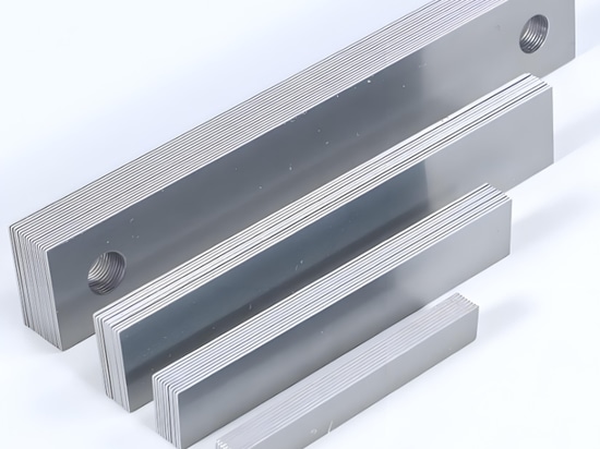
Highly Permeable Silicon Steel Sheets (CRGO): Using 0.23mm thick CRGO (e.g., 30JG120) with a Goss texture proportion exceeding 85% reduces hysteresis losses by 40%-60%. The unit loss is only 1.10W/kg (at 1.7T magnetic density), 25% lower than traditional silicon steel.
Coating Technology: Phosphate-silicate composite coatings increase interlaminar insulation resistance to 100Ω·cm², reducing eddy current losses.
Amorphous Alloys: Although losses are as low as 0.20W/kg, their high cost (cost index of 3.5) and low fill factor (0.85) limit their use to specific scenarios.
(2)Structural Innovations
Mitered Joint Design: A 45° joint angle reduces local magnetic flux density from 1.8T to 1.5T, lowering losses by 35% and temperature rise by 4-6K.
Step-Lap Joint: A five-step lap joint with a 0.5mm gap reduces no-load current by 12% and suppresses transverse leakage flux by 50%.
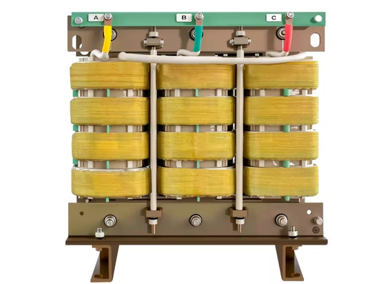
2.Winding System Design: Electro-Thermal Coupling Optimization
(1)Conductor Selection
Flat Copper Wires: Transposed conductors with a width-to-thickness ratio of 3:1 reduce AC resistance by 15%, with a transposition pitch ≤8mm (for currents >1000A).
Insulation System: Nomex® insulation paper (withstanding 180°C) achieves a fill factor of 0.85, balancing heat dissipation and insulation.
(2)Thermal Field Control
Axial Split Windings: Paired with 6mm oil ducts, oil flow velocity increases to 0.25m/s, reducing axial temperature differences from 20K to 8K.
End Shields: Copper electrostatic rings reduce end field strength by 43% (from 3.5kV/cm to 2.0kV/cm), lowering the risk of local overheating.
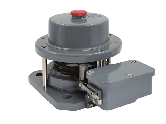
3. Cooling System Upgrade: From Passive to Intelligent
(1)Oil Path Optimization
Turbulent Flow Design: Oil duct widths of 6-8mm (Reynolds number Re≈4000) improve heat transfer coefficients by 30%-50%.
Synthetic Ester Oil: With 15% lower viscosity than mineral oil, heat exchange efficiency improves by 20%.
4.Intelligent Regulation
Variable-Frequency Oil Pumps: Reduce power consumption by 50% under partial loads.
Heat Pipe Technology: Hotspot regions can handle heat flux up to 50W/cm², adapting to dynamic loads.
5.International Standards and Future Trends
Current Standards: IEC 60076-14 requires real-time hotspot temperature monitoring; China's GB 20052-2020 mandates a 20% reduction in no-load losses for Tier 1 energy-efficient transformers.
Technological Frontiers:
oDigital Twins: Real-time temperature field prediction to optimize cooling strategies.
oNanofluids: Improve heat transfer coefficients by over 30%.
oHigh-Temperature Superconductors: Eliminate copper losses, revolutionizing temperature rise reduction.
Conclusion
By comprehensively adopting the above measures, the temperature rise of oil-immersed transformers can be reduced by 15-25K, efficiency can improve by 0.8%-1.5%, and annual carbon emissions can decrease by 5-10 tons (for a 1000kVA transformer). It is recommended to use multi-physics simulation platforms for lifecycle temperature rise management.
About Lushan Electronics
With 50 years of expertise in transformer/reactor manufacturing, we serve industries like renewables, healthcare, and rail transit. CE/TÜV-certified, we deliver tailored solutions balancing performance and cost globally.
[Website: www.lstransformer.com| Contact: [email protected]]