
#Product Trends
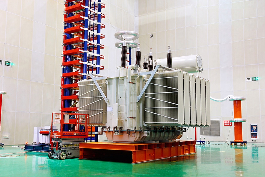
Rectifier Transformer offering solution for converts alternating current (AC) into direct current (DC)
Rectifier Transformer
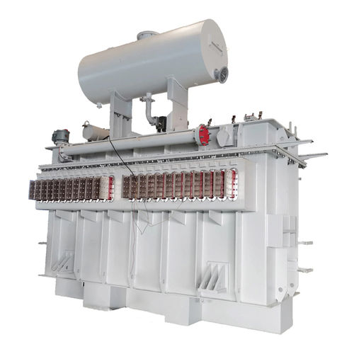
Rectifier Transformer is a specially designed transformer that supplies AC power to a rectifier system, which converts alternating current (AC) into direct current (DC). Unlike conventional power transformers, rectifier transformers are engineered to withstand harmonic currents, DC bias, unbalanced loading, and severe thermal stresses associated with rectifier operation.
Rectifier transformers are widely used in electrochemical industries, metal processing, DC motor drives, renewable energy systems, mining, railways, and HVDC transmission.
Working Principle
The transformer receives AC power from the utility network and converts it to the voltage required by the rectifier. The rectifier, using diodes or thyristors, then converts the AC output into DC.
The process is:
1.High-voltage AC power enters the primary winding.
2.The transformer steps the voltage up or down as required.
3.Multiple secondary windings may provide phase-shifted outputs.
4.The rectifier converts the AC into DC.
5.Filters and smoothing reactors reduce ripple before supplying the DC load.
Main Components
Magnetic Core
·High-grade CRGO silicon steel core
·Step-lap core construction for reduced losses and noise
·Designed to minimize additional losses caused by harmonics
Windings
·Copper or aluminum conductors
·Heavy-duty insulation system
·Reinforced mechanical construction for short-circuit withstand
·Multiple secondary windings for multi-pulse rectifier systems
Insulation System
·Oil-paper insulation (oil-filled types)
·Class F or Class H insulation (dry-type versions)
·Enhanced insulation against harmonic heating
Cooling System
Typical cooling methods include:
·ONAN – Oil Natural Air Natural
·ONAF – Oil Natural Air Forced
·OFAF – Oil Forced Air Forced
·OFWF – Oil Forced Water Forced
·AN – Air Natural (dry type)
·AF – Air Forced (dry type)
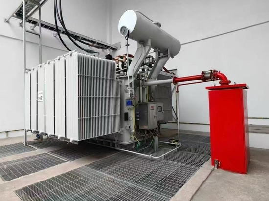
Large industrial rectifier transformers typically use ONAF, OFAF, or OFWF cooling.
Typical Technical Specifications
·Rated Power: 100 kVA – 250 MVA
·Primary Voltage: 3.3 kV – 400 kV
·Secondary Voltage: 100 V – 33 kV
·Frequency: 50 Hz / 60 Hz
·DC Output: Depends on rectifier configuration
·Cooling: ONAN, ONAF, OFAF, OFWF, AN, AF
·Insulation Class: A, F, H (dry type)
·Vector Group: Customized for rectifier duty
·Impedance: Optimized for harmonic performance
Types of Rectifier Transformers
·Single-Phase Rectifier Transformer
·Small DC power supplies
·Battery charging systems
·Laboratory equipment
·Three-Phase Rectifier Transformer
·Industrial rectifier systems
·Large DC motor drives
·Electrolysis plants
Multi-Pulse Rectifier Transformer
Common pulse configurations include:
·6-pulse
·12-pulse
·18-pulse
·24-pulse
·36-pulse
Higher pulse numbers reduce harmonic distortion and improve power quality.
Key Features
·Designed for nonlinear loads
·High resistance to harmonic heating
·Multiple secondary windings
·Excellent short-circuit strength
·Low stray losses
·High overload capability
·Stable voltage regulation
·Long service life under demanding industrial conditions
Applications
·Electrolysis plants (chlor-alkali, hydrogen production)
·Aluminum smelting
·Copper and zinc electrowinning
·Steel manufacturing
·DC motor drives
·Mining equipment
·Industrial furnaces
·Railway traction substations
·Battery charging systems
·Renewable energy conversion systems
·High-voltage direct current (HVDC) converter stations
Advantages
·Reliable AC-to-DC power conversion
·Supports high-current DC loads
·Optimized for harmonic-rich environments
·Improved efficiency for rectifier applications
·Flexible voltage and phase-shift configurations
·High mechanical and thermal durability
Design Considerations
Rectifier transformers are designed to address:
·Harmonic currents generated by rectifiers
·Increased eddy-current and stray losses
·DC magnetization effects
·High thermal loading
·Voltage regulation requirements
·Electromagnetic forces during short circuits
·Compatibility with converter pulse configuration
Applicable Standards
Common international standards include:
·IEC 60076 – Power Transformers
·IEC 61378 – Converter Transformers
·IEEE C57.18.10 – Practices and Requirements for Rectifier and Furnace Transformers
·IEC 60146 – Semiconductor Converters
·Customer-specific industrial specifications
Typical Installation
A rectifier transformer installation typically includes:
·High-voltage switchgear
·Rectifier transformer
·Diode or thyristor rectifier bridge
·Smoothing reactor
·Harmonic filters
·DC switchgear
·Protection relays
·Cooling equipment
·Monitoring and control systems
Summary
A Rectifier Transformer is a purpose-built transformer for supplying AC power to rectifier systems, enabling efficient conversion to DC. Its robust thermal and mechanical design, harmonic tolerance, and customizable winding configurations make it essential for demanding industrial applications such as electrolysis, metal processing, traction systems, and HVDC. Compared with a conventional transformer, it offers superior performance and reliability when serving nonlinear DC loads.