#Product Trends
Introduction to Sine Pump
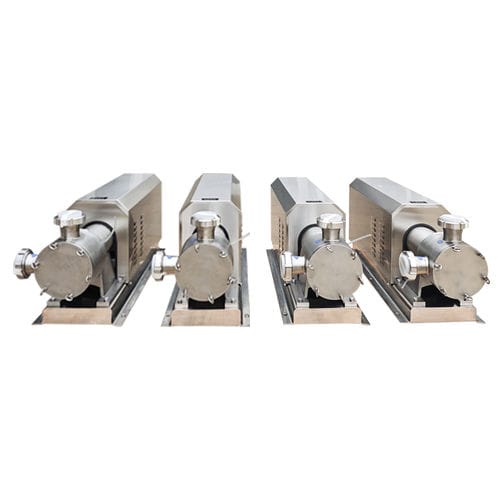
The Sine Pump, also known as a Cam Rotor Pump, Three-Lobe Helical Pump, or Sine Rotor Pump, is a rotary positive displacement pump that operates on the principle of meshing cam rotors. Its core lies in the uniquely designed "Sine Curve" profile rotor
Working Principle
The Sine Pump operates based on two (or three) "Sine Curve" profile helical rotors rotating in opposite directions, synchronized by timing gears.
Suction Phase: As the rotors turn, at the inlet side, the rotor lobes disengage from the meshed state. This creates a sealed cavity between the rotor lobes and the pump casing that increases in volume, generating a vacuum that draws the medium into the cavity.
Transfer Phase: The entrapped medium is enclosed in "pockets" formed by the rotor lobes and the pump casing. Through the continuous rotation of the rotors, these medium pockets are conveyed axially along the helical path of the rotors towards the outlet in a stable, continuous flow. The process is non-reciprocating.
Discharge Phase: At the outlet side, the rotor lobes re-mesh, causing the volume of the sealed cavity to decrease. This gently squeezes and expels the medium while effectively preventing backflow.
This "Sine" profile design ensures the rotor contact line moves slowly and continuously during operation, significantly reducing flow and pressure pulsation, resulting in an almost "pulsation-free" transfer.
Key Features
Extremely Smooth & Low Shear: Delivers exceptionally smooth flow and pressure output with minimal pulsation (typically <1%). Imparts very low agitation and shear force to the medium, making it ideal for handling shear-sensitive, froth-prone, or solids-containing products (e.g., jams, yogurt, live cultures, polymer solutions).
Strong Self-Priming & Dry-Run Tolerance: Offers good self-priming capability with high suction lift. Allows for short periods of dry running without damage (unlike centrifugal pumps), enhancing operational reliability.
Excellent Abrasion Resistance & Passing Ability: The large cavity and slow meshing action enable it to handle high-viscosity fluids (up to 1 million cP) and media containing relatively large solid particles (up to 30%-40% of rotor diameter) or long fibers, with low risk of clogging.
High Efficiency & Good Reversibility: High volumetric efficiency leads to relatively low energy consumption. The symmetrical pump design often allows flow reversal simply by changing the drive direction, without re-piping.
Ease of Maintenance: Features a front/rear cover plate design allowing quick access to the rotor chamber and seals without disconnecting pipelines, facilitating easy inspection and maintenance.
Typical Configuration
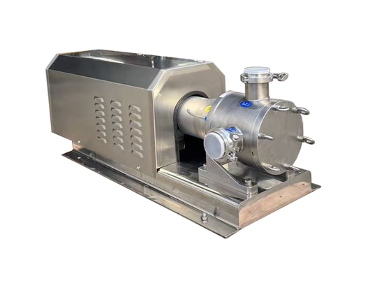
A complete Sine Pump system typically includes the following core components:
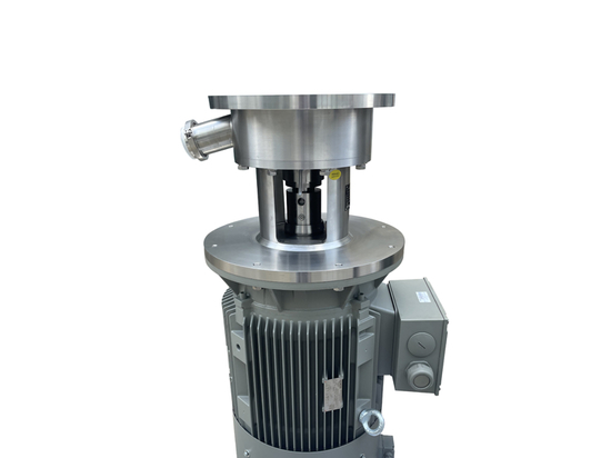
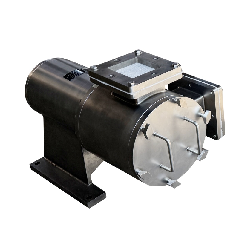
Pump Head:
Rotors: The core components, usually designed as 2 or 3-lobe helical rotors. Materials are selected based on the medium, including stainless steel (304, 316L), wear-resistant cast iron, special alloys, or coated rotors.
Casing/Body: Houses the rotors and forms the working chamber. Material matches the rotors, commonly stainless steel or cast iron.
Shaft Sealing System: Chosen according to pressure, temperature, and medium. Common options include:
Mechanical Seals: Single or double mechanical seals, optionally with flush/cooling systems for demanding duties.
Packed Gland Seals: Suitable for abrasive, particle-laden media, adjustable.
Magnetic Drive (Sealless): Provides complete leak-free operation for hazardous, toxic, expensive, or absolutely zero-leakage applications.
Drive & Connection:
Gear Reduction Motor: Standard configuration providing stable power. Speed can be adjusted (via a VFD) for precise flow control.
Drive Arrangement: Typically direct-coupled for a compact design. Larger pumps may use a separate base-mounted arrangement with a coupling.
Connections: Inlet/Outlet flanges per standard (e.g., DIN, ANSI, GB), sized to match piping.
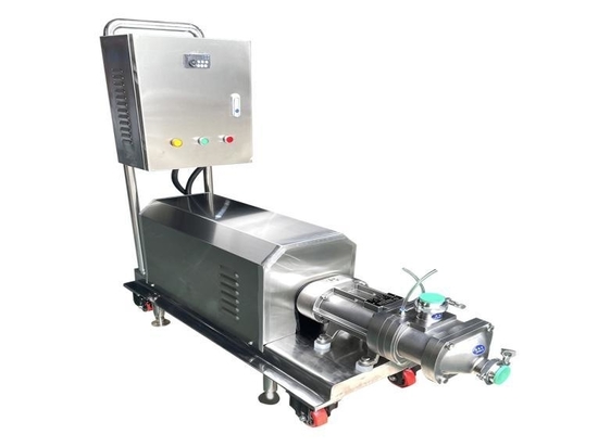
Ancillaries & Control (Optional):
Relief Valve: Installed on the discharge line to prevent system overpressure and protect the pump and piping.
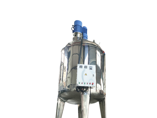
Jacketing: The casing can be designed with a jacket for steam, hot water, or coolant to maintain medium temperature or viscosity.
Variable Frequency Drive (VFD) & Control System: Used to adjust speed for precise flow/pressure control, integrating start/stop, alarm, and protection functions.